Meshes
The finite element method works by breaking down a real object into a large number (1,000s to 100,000s) of elements, such as little tetrahedra or cubes, called a mesh. Set mathematical equations predict the behavior of each element. The computer combines all of the individual elemental behaviors to predict the behavior of the full part or assembly.
The quality of a surface mesh, and the shapes of the solid elements, affect the accuracy of your simulation results. Also, the mesh density (that is, the number of elements per unit volume) affects the accuracy of the results. Pay attention to the quality of the mesh, and local mesh refinement, to maximize the accuracy of your results through mesh convergence techniques.
Autodesk Fusion provides automated mesh generation along with both global and local settings for the mesh size, mesh quality, element order, and other options.
- Mesh settings apply to all components.
- Local mesh controls apply to selected entities.
- Each simulation study has its own mesh settings.
A good mesh balances precision and computing time. Quality meshes converge quickly, produce accurate results, and do not produce errors. The majority of the meshing process involves specifying the appropriate mesh settings.
Nodes and elements
Before solving a Fusion analysis, the geometry is broken up into small pieces called elements. The corner of each element is a node. The calculation is performed at the nodes. Additionally, nodes may be included at the midpoint along the edges of the elements. These elements and nodes make up the mesh.
Solution accuracy depends on a good mesh, and Fusion automates much of the mesh creation process to help you create a good mesh for your simulation.
A node is a coordinate location in space where the degrees of freedom (DOFs) are defined. For structural analyses, the DOFs represent the possible movement of the point due to the loading of the structure. The strain in the material is determined from the relative motion of the nodes, and the stresses are calculated based on the strains and the material properties. For thermal analyses, the only DOF is the temperature at each node. The heat flux is then determined based on the temperature distribution and the thermal conductivity of the material. The DOFs also affect which forces and moments are transferred from one element to the next. The results of a finite element analysis (deflections, stresses, temperatures, heat flux rate) are given at the nodes.
In the real world, a point moves in six different directions—translation in X, Y, and Z, and rotation about X, Y, and Z. In FEA, a node can be limited in the calculated motions for various reasons. For example, there is no need to calculate the out of plane translation on a 2D element. It is not a 2D element if its nodes can move out of the plane. Additionally, nodal rotations are not considered for solid elements. All deformation in solid elements is the result of nodal translations only. However, planar and line elements typically support rotational DOF.
The DOF of a node relates what types of forces, restraints, or heat flows are transmitted through the node to the element. A force, axial or shear, corresponds to a translational DOF because the stiffness of the element determines how far the node moves when subjected to a particular load. A moment corresponds to a rotational DOF. Thus, to transfer a moment about a certain axis, the node must have a rotational DOF about the axis. If a node does not have that rotational DOF, then applying a moment to the node has no effect on the analysis. Likewise, restraining a node with a rotational boundary condition has no effect if the node lacks the ability to transmit the moment.
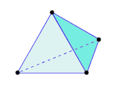
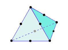
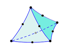
An element is the basic building block of a finite element analysis. There are different element types and their usage depends on the model and on the analysis type. Currently, all solid elements in Fusion are tetrahedral (consisting of four triangular faces and six edges each). Linear tetrahedral elements have four nodes. Parabolic tetrahedral element add a midside node along each edge, resulting in a total of ten nodes per element. There are two variations of Parabolic tetrahedral elements—with and without curved edges.
Table 1: Tetrahedral Element Variations.
 |
 |
 |
| Linear Tetrahedron | Parabolic Tetrahedron | Parabolic Tetrahedron with Curved Edges |
| (4 Nodes) | (10 Nodes) | (10 Nodes) |
An element is a mathematical relationship that defines how the degrees of freedom of one node relate to the next node. This mathematical relationship also define how the deflections create stresses.