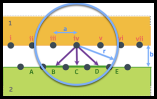
Example of Maximum Activation Distance
The maximum activation distance determines which contact elements (purple lines) are created at the onset of the analysis.
Note: This process creates contact elements at the beginning, but unlike mesh elements, you can't see them on the model.

Figure 1. Determining the maximum activation distance.
Let's say the two parts are separated by 2 mm (b) and the mesh size is 4 mm (a). To span the gap, you need a theoretical distance of the square root of (a^2+b^2), which equals 4.5 mm.
You then set the Max. Activation Distance (r) to 1.1 to 1.2 times the theoretical distance to account for margin of error, which is 5 mm.
With this setting, if a node on the secondary face is within 5 mm of a node on the primary face, the system creates a contact element.
Note: No contact elements are created during the analysis, even if the parts slide relative to each other.
Important:
If displacement eliminates the gap but there is no sliding, then node iv contacts element C and transmits a force to it. Node iv does not transmit a force to any other element in this scenario.
If the parts slide so that node iv moves over element B, then contact is detected when node iv tries to penetrate element B.
If node iv moves a distance larger than the activation distance, such as node iv over element A, then there is no contact element, and the node can pass through the element.