Maximum activation distance
Imagine you have a model with two faces separated by a small gap. You expect these faces to touch when applying a load. To test this in a simulation, you need to set a maximum activation distance. This setting prevents one face from penetrating the other upon contact.
The maximum activation distance specifies the allowable distance between nodes on two faces for contact recognition. It's recommended setting this when using offset bonded or separation contact types.

Figure 1. Maximum activation distance, r
Let's say you want to recognize contact between node iv and elements (B), (C), and (D). In this case, the maximum activation distance is 'r'. This distance 'r' is the measurement from 'node iv' on the primary face to the nodes surrounding elements (B), (C), and (D) on the secondary face.
Note: This parameter is useful when there is only a small gap between parts. If a body penetrates another after analysis, consider increasing the maximum activation distance or try a nonlinear static stress analysis.
Maximum activation distance setup
Manual Max. Activation Distance: If you don't use the Automatic Max Activation Distance, you can manually enter a value for the Max. Activation Distance. This forms contact elements between nodes on both faces within the specified distance.
Automatic Max Activation Distance: If contact faces touch, there's no need to manually enter a value for the Max. Activation Distance. Instead, use the Automatic Max Activation Distance. Fusion will automatically calculate this based on a fraction of the model size.
Automatic Max Activation Distance is disabled and no value is entered: If the Automatic Max Activation Distance is disabled and no value is manually entered for the Max. Activation Distance, the model will not form any contact elements between nodes on faces. This setting assumes that no contact is expected between faces.
Note: The Max. Activation Distance must be set up before the solve starts, that is, before the model is deformed. It is recommended for users to manually set the Max. Activation Distance.

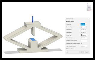
Figure 2. Maximum activation distance value is set to be slightly larger, approximately 1.1 to 1.2 times more than a 10-mm gap, to accommodate a margin of error.

Figure 3. Undeformed model

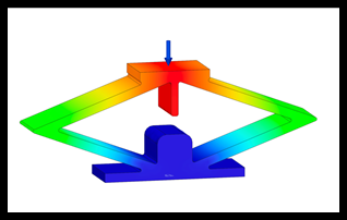
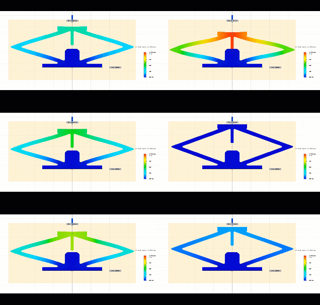
Figure 4. No penetration because maximum activation distance is specified.

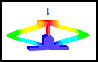
Figure 5. Animation showing penetration because maximum activation distance is not specified.