Activity 4: Clone the study, modify the setup, and rerun
In this activity, you
- Clone the study and move the injection location, to improve the appearance of aesthetic faces
- Clone the model and child study, to make wall thicknesses more uniform and improve the likelihood of filling
- Run the new studies to compare the result of the changes with the original study.
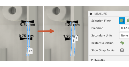
Hedge trimmer original model (left) and Hedge trimmer model with thicker rib (right).
Prerequisties
- Activity 3 is complete.
Steps
Clone the original study, so you can compare the results of the new study with the original study.
On the Setup tab, in the browser, right-click Study 1- Injection Molding Simulation to activate the contextual menu.
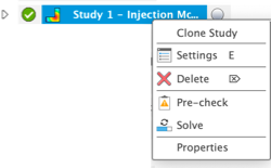
In the contextual menu, click Clone Study.
Rename the new study 'Move inj loc' to distinguish it from the original study.
- Click twice, slowly, on the new study name to enable editing.
- Type in the the new name.
Move the injection location from the top of the flat face, to a central position at the base of the vertical face of the handle:
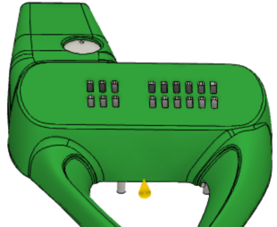
In the canvas, select the injection location glyph, then right-click to activate the marking menu.
Note: The injection location glyph turns blue when selected.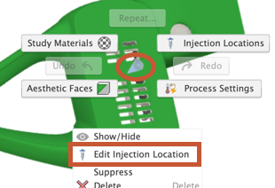
In the marking menu, select Edit Injection Location to open the Edit Injection Location dialog.
In the canvas, select the blue circle at the base of the injection location glyph and drag it to a central position at the base of the vertical face.
In the Edit Injection Location dialog, click OK to accept the change and close the dialog.
Clone Simulation Model 1, and its Study 2 - Move inj loc, in preparation for modifying the thickness of the problem rib.
- In the browser, right-click Simulation Model 1 to activate the contextual menu, and select
 Simplify.
 - In the Simplify Solid tab, in the browser, right-click Simulation Model 1 to activate the contextual menu, and select Clone Simulation Model
- In the Clone Simulation Model dialog, deselect Study 1 - Injection Model Simulation, then click OK.
- In the Simplify Solid tab, click
 Finish Simplify to return to the Setup tab.
- In the browser, right-click Simulation Model 1 to activate the contextual menu, and select
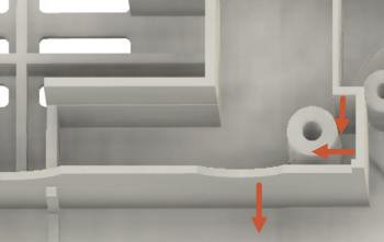
Increase the thickness of the three ribs shown in the image, by 0.5 mm in the directions shown.
In the Simplify Solid tab, click
 Press Pull to open to the Press Pull dialog.
In the canvas, select one of the faces, confirm the direction, and enter 0.5 mm as the Distance.
In the Offset Face dialog, click OK to accept the change and close the dialog.
Repeat the process with the other two faces, increasing their thickness by 0.5 mm in the direction shown by the red arrows.
In the Simplify Solid tab, click
 Finish Simplify to return to the Setup tab.
For each of the two new studies, check that they are setup and ready to solve, then start the analyses.
Click
 (Simulation workspace > Setup tab > Solve panel > Pre-check), to open the Pre-check dialog.
Notice that there is a yellow warning icon which indicates that although the study can be solved, some inputs may not be ideal. In this case, althogh we have moved the injection location away from the center of an aesthetic face, it is still on an aesthetic face, hence the warning. It's current location is not very visible to a consumer, and the mark it will leave is in an acceptable location.
In the Pre-check dialog, click Close once you have reviewed the suggestions.
Click
 (Simulation workspace > Setup tab > Solve panel > Solve), to open the Solve dialog.
In the Solve dialog, deslect both of the new studies, then click Solve 2 Studies to run tthem and close the dialog.
*Note: Meshing and solving the analysis can take several minutes.
When the analyses are complete, click Close to close the Job Status dialog.
Activity 4 summary
In this activity, you
- Cloned the original study and moved the injection location
- Cloned the original Simulation model and child study, and made the wall thicknesses more uniform
- Ran the new studies.