| File/s needed: |
| Click to download the Advanced [US Units] tutorial model files. |
Items can be added to the plan and connected individually, or drawn as a connected "Treatment Train " using the Add Train tool in the Build menu. The former approach, adding items individually, will be used here. The treatment train begins with the Inflow Area of the Developed Area that drains to a Bioretention SWC, from here the site runoff is conveyed to a Dry Pond.
- Open the file ID_US_Advanced_Tutorial_Ch3.iddx or continue working from your previous file.
- Turn off the visibility of the
surface
map by clearing the Surface layer check box in the Tree View panel.

- Make sure you are still working in the
Developed Phase.

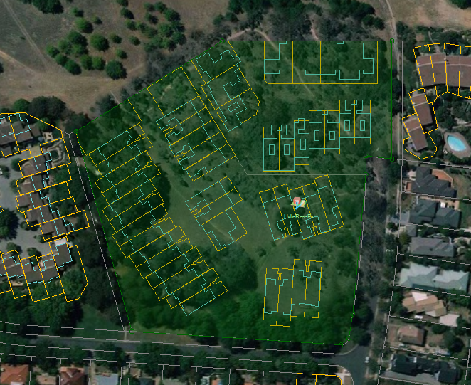
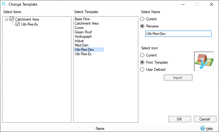
- Right-click on the Inflow Area and select
Change Template. Choose the
Urb-Res-Dev Template and rename the area. Click
OK.
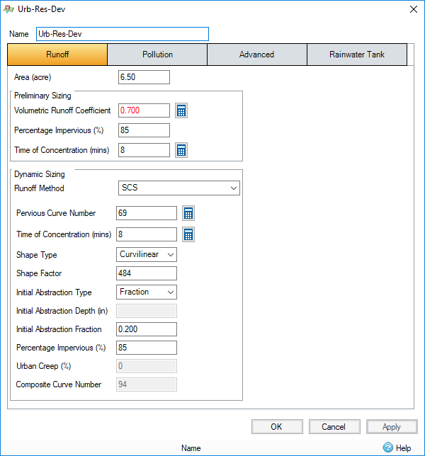
- Double-click the inflow area (or right-click and then select Edit) to edit the Developed inflow area. Note the high percent imperviousness and shorter time of concentration. No changes are required due to the use of the developed landuse template, though the calculators could be used for assistance when making updates to Curve Number and Time of Concentrations values.
-
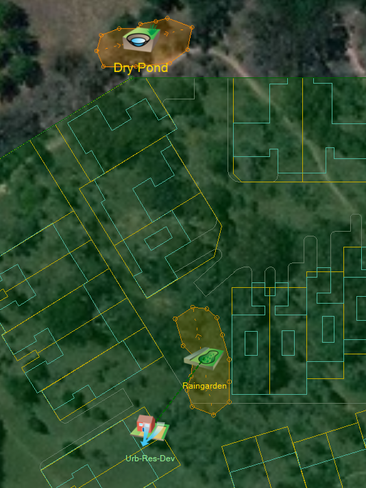
Now we are going to add the drainage network. Turn off Snap on the Plan ribbon. Under the Build ribbon, select the Add Stormwater Control option and then the Raingarden SWC. Move the pointer to the location on the site where the SWC will be installed and use the left mouse button to draw the outline of the Raingarden (similar to the outline shown in the figure below). When you are done drawing the polygon, use the right mouse button to end the drawing action.
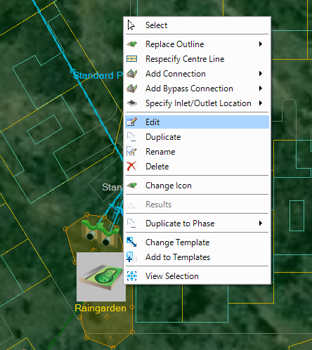
Note: SWC outlines can be redrawn at any point by right-clicking the SWC and selecting Replace Outline. - If the Inflow icon is in the way, select the Inflow icon then hold Shift on the keyboard and drag the icon on screen to move it without moving the Area.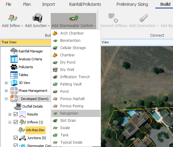

- Under the Build ribbon, select the Add Stormwater Control option and then the Dry Pond SWC. Move the pointer to the location on the site where the Dry Pond SWC is installed and use the left mouse button to draw the outline of the Dry Pond SWC (similar to the outline shown in the figure below). When you are done drawing the polygon, use the right mouse button to end the drawing action.

-
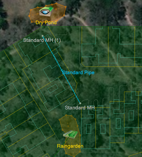
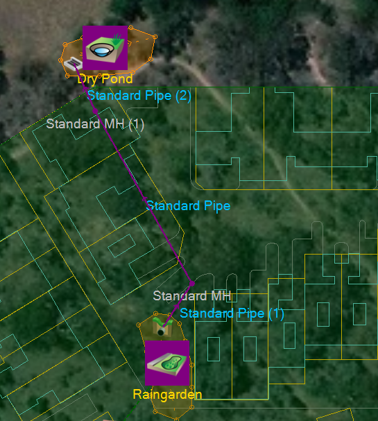
Under the Build ribbon, select the Add Network option and then select Standard MH (1) from the Next Item drop-down menu. Move the pointer to the location on the site where the first manhole will be installed and use the left mouse button to place the manhole. You will notice that the software automatically assigns the inflow area to the junction when it is placed in Plan View. Next select Standard Pipe from the Add Connection drop-down menu and continue placing the manholes as shown below. Press the Esc key to end the run of pipes.

-
Right-click the northern edge of Raingarden (where the under drain will exit the SWC and connect to adjacent MH) and select Add Connection, choose the Standard Pipe template. Then left-click the adjacent Manhole.
Note: Holding the Shift key and clicking on the Plan View where there are multiple objects will allow you to choose which one is selected.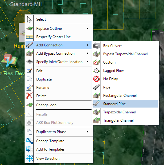
 Note: Note that the Standard Pipe template consists of a 12 inch diameter pipe with roughness of 0.013. This and other templates can be viewed by browsing to File, Templates.
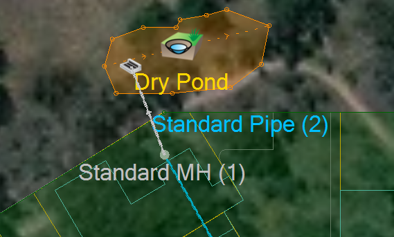
 - Then add a Standard Pipe between the northern MH and the side of the Dry Pond SWC, choose the
Outlet from the radial menu when it pops up. The result should look as shown.
- To understand what elevations were adopted and how well the treatment system connects, right-click the Flow Paths item at the bottom of the Tree View and select Add (or alternatively by right-clicking the Raingarden and select Add Flowpath/Profile) then select the Raingarden icon and then click the Dry Pond icon. Hit the Esc key in order to stop tracing.

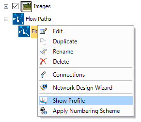
- Right-click the new Flow Path and select Show Profile (alternatively, select the Flow Path under View, Profiles) to display a profile of the flow path.

-
We currently only have the underdrain from the Raingarden SWC outfalling into a 12 " pipe and into the adjacent MH. We need to specify the High flow bypass weir for this facility. Close the Profile view.
-
Click to select the Raingarden stormwater control. Right-click the north eastern side of the SWC and select Add Connection. This time, select Bypass Trapezoidal Channel. When you connect this to the adjacent MH you will see inlet options for the manhole, either the existing inlet or a new inlet can be selected. As we are not restricting inflow into this MH from either connecting pipe, we can select the existing inlet. Press the Esc key to end drawing connections.
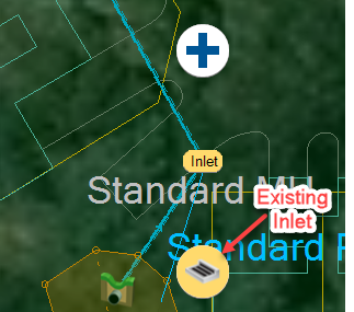
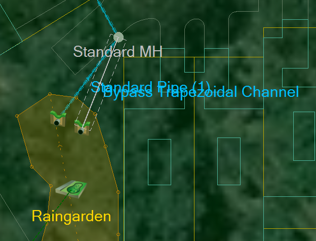 Note: If Inlets and Outlets fall outside of the SWC, the Inlet and Outlet icons will disappear automatically and the links will connect directly to the SWC icon. The Inlets/Outlets are not deleted, only removed from the graphical view, they can be redrawn by right clicking on the SWC icon and choosing the Specify Inlet/Outlet Location command.
 -
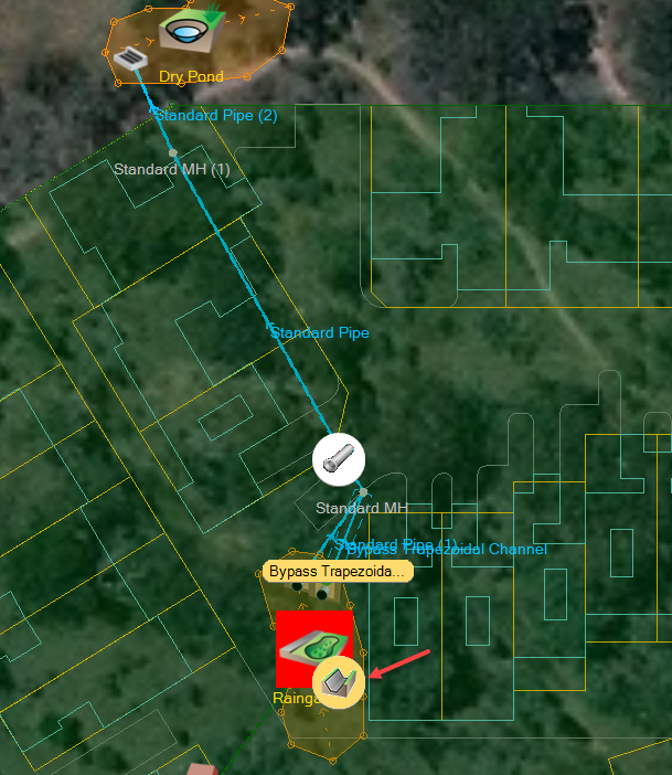
To view the newly added Channel in Profile a second flow path will need to be drawn. Right-click the Flow Paths option, select the + symbol and select the Raingarden icon and the Dry Pond Icon. Since the previously traced flow path follows the underdrain of the Bioretention system, this time select the Bypass Trapezoidal Channel when prompted.
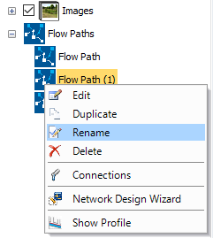
- Once added, right-click the newly added Flow Path (1) and select Rename. Change the name to Bypass Route.
- Right-click the Bypass Route and select Show Profile.
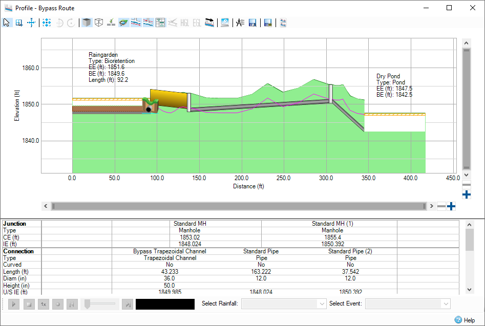
- We can easily see the bypass channel is not at an appropriate elevation, double-click the Connections option within the Tree view to open the Connections form.

- Edit the Bypass Channel Elevations to be as shown, we will also update the Raingarden. Upstream Cover Elevation: 1853 ft; Upstream Invert Elevation: 1852 ft.
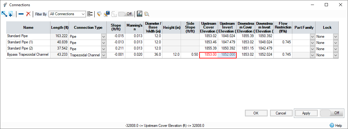
- Click OK and the Profile view will be updated. Close the Profile.
- We will now update the elevation of the SWC to match. Edit the Raingarden SWC by double-clicking the icon (or by right-clicking and selecting Edit). Use Click to Show Image(s) in order to show a diagram of the Stormwater Control or to view various real world photos of this facility. The Depth and Side Slope are set in the template and the elevations and area are calculated from the surface data (which has been pre-loaded in this model), they may also be defined by the user. The values may differ slightly depending on exactly where you have clicked during the Build options.
- Manually set the Exceedance Elevation
to 1853.0. Note the red text designating a manual input. Switch to the Outlets tab.

- Go to the Outlets tab. Change the name of outlet (1) to be called Bypass, and then change the outlet type to Weir. Set the Crest Elevation
to 1852 (one ft above the base elevation) and set the Width as 1.0 ft as an initial configuration.

- Go to the
Filtration Layers tab and then click the calculator icon. In the
Soil Type Properties dialog, enter
6.2 for Field Capacity (%) and 2.4 in Wilting point (%).


- Click OK to close the Raingarden.
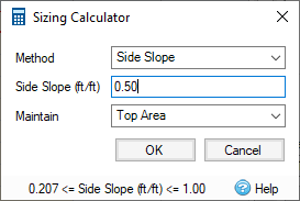
- Edit the Dry Pond SWC. Note by using the template, we have a 5 ft deep pond with a top area automatically set based on how the outline was drawn. The base area needs to be set. Use the Sizing Calculator and select
Side Slope, input 0.5 ft/ft (1:2 slope). We will maintain the Top Area. Select OK and note how the depth-area-volume table and associated schematic have been updated.

- Select the Outlets tab, select the + button and from the available Outlet Types select the Multiple option. As is common for a Pond SWC, we will have a minor event orifice outlet as well as a major event weir control.
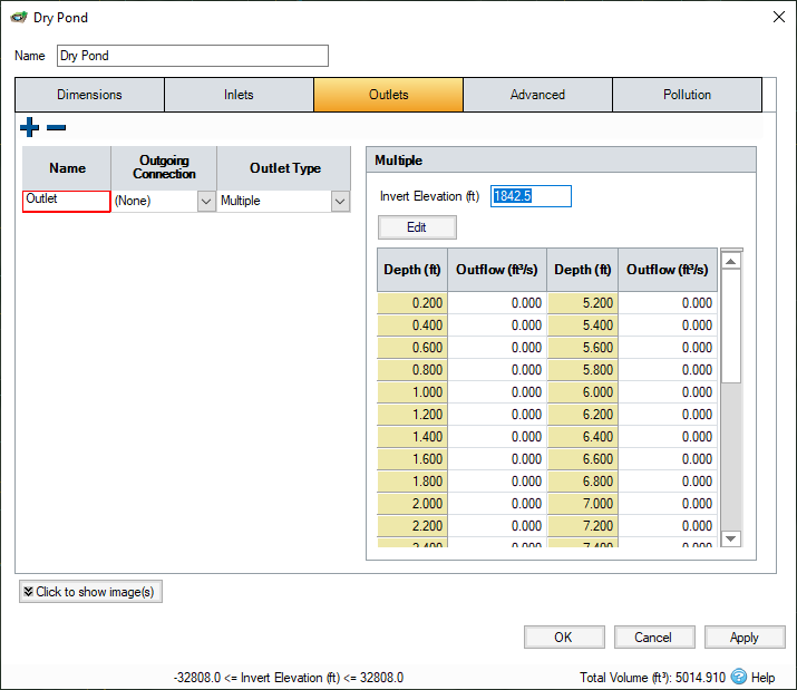
- We will be using the pond to control the initial runoff by allowing infiltration. This will help us achieve Runoff Reduction and prevent the Water Quality event discharge from leaving the site. Therefore add 1ft to the Invert Elevation automatically picked up as the Base Elevation of the Pond. This will place our outlet control 1 ft above the base preventing any discharge until that depth is reached.

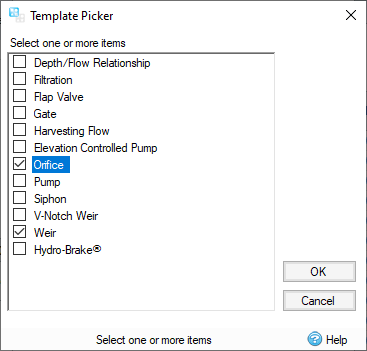
- Then select the Edit button above the depth-outflow table. Select the + icon, select Orifice and Weir from the list.
- We could manually enter some starting values for the Orifice and Weir or we could use the wizard calculator to help. Use the > button next to the Control List table.Enter the following design depth-flow values into the wizard calculator.
- Orifice: 1 ft Design Depth; 0.9 Design Flow
- Weir: 3 ft Design Depth; 3.2 Design Flow
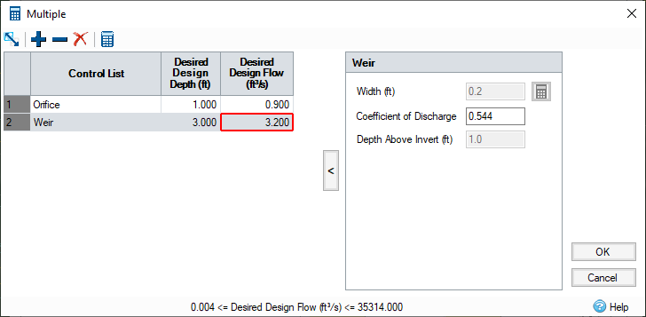
- Click the calculator button Solve for displayed controls. Click on each row of the Control List table to see the results. 0.5 ft has been calculated as the Orifice diameter and 0.2 ft as the Weir width.
- Click OK and see the Depth – Outflow table populated.
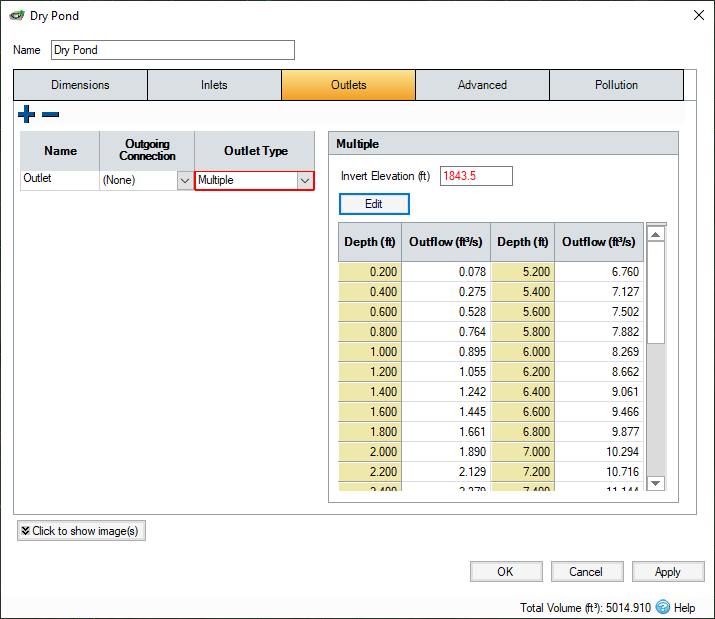
- Click OK to close the Dry Pond.
- Now that the Treatment Train is laid out, you can review the
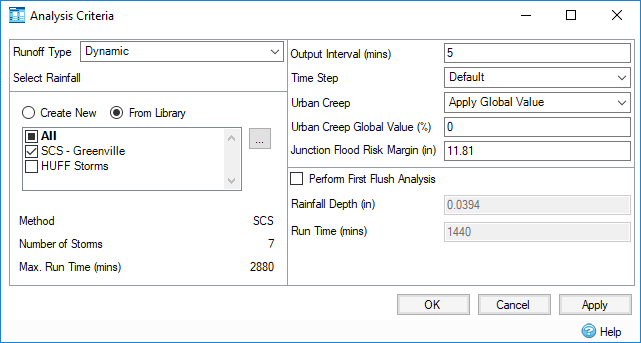
Analysis Criteria and
Rainfall set up by browsing to the Analysis ribbon and selecting Analysis Criteria.

Set the criteria as seen below. Further information about the Analysis Criteria dialog and the Rainfall Manager can be found on the given Help topic Analysis Criteria.
- Run the simulation by selecting Go under the Analysis tab.
