Chamber stormwater controls are underground storage solutions which use pre-built chambers to house the stored volume.
Total Volume
The Total Volume value shown in the bottom-right corner of the data form shows the volume available in the system up to the Freeboard elevation.
Dimensions
The Dimensions tab has the following fields:
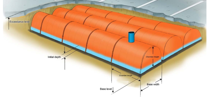
Exceedance Elevation - Represents the elevation (above datum) of the stormwater control above which flooding is reported. This may be the elevation that interacts with the ground surface or the top of an embankment, whichever is higher. If a Surface Data model (TIN) is present the Exceedance Elevation will automatically be picked up from the center of the icon or from the lowest point on the perimeter if an outline has been drawn. This allows a Status of Flood Risk to be assigned to the system on the Summary. Above the Exceedance elevation, water will be stored above the ground and then allowed to drain back into the network. The ponding area used for the flooded volume is the area the Chamber occupies on the plan.
Depth - This is the depth of the input data, including chambers and Embedded dimensions. This can be less than the difference between the Exceedance and Base Elevations; in this case, the system is assumed to be buried. The depth is kept up to date at all times, and can be changed by adjusting the parameters of the chamber being used, or the amount of Embedded above or below the chambers.
Base elevation - Represents the elevation (above datum) of the base of the Stormwater control.
Number of Chambers - This specifies how many chambers are present within the system. This number is the primary adjustable value for changing the contained volume in the Stormwater control.
Number of Rows - Details the number of rows to be used by the structure. This value is rarely adjusted by the system, and is used to generate a shape for the structure. Rows will always be evenly sized, as far as possible.
Distance Between Rows - If rows are not to be packed tightly to each other, the space between them can be specified. This allows the structure to more accurately represent the built site, as well as to account for any additional fill material needed.
Chamber Specification
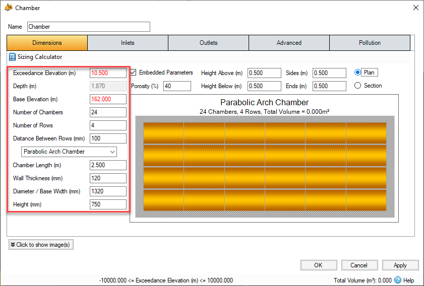
A single chamber is a shaped structure that is used to hold the water underground. Chambers typically come in one of three categories based on their cross section; An elliptical arch, a complete circle (such as a pipe), or a Box Culvert. All chambers within a drainage system are assumed to be identical. If Custom is selected, a cross section can be input manually via the Define Cross Section form. The resulting width and height will be visible in the usual text boxes - these values are for reference only.
Chamber Type - This drop-down menu allows you to choose the category of Chamber you would like to specify. If none of the available options are suitable, a cross section can be manually input using the Custom option.
Chamber Length - This specifies the length of a single chamber.
Wall Thickness - Can be used to set a thickness for your Chamber walls; this will be excluded from Volume calculations.
Diameter / Base Width - The internal horizontal width of the structure. The maximum internal width should be used.
Height - The internal vertical height of the structure. Must be specified for all chambers other than pipes.
Corner Splay - The corner splay to use. This is only an option for Box Culvert chambers. If desired, this can be left at 0 to create a simple square or rectangular chamber.
Define Cross Section - This will open the Define Cross Section window to allow specification of the chamber manually.
Embedded Parameters
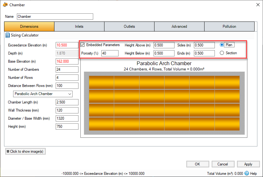
A chamber Drainage system can be created with or without regard for the surrounding substrate. If Embedded Parameters are disabled, the only volume available is that provided by the chambers. With Embedded enabled, the chambers are assumed to be surrounded by a fill material with the given porosity , with water being able to move between the two mediums. Total retention volume includes the available storage within the embedded material.
Porosity - The porosity of the Embedded Fill material.
Height Above/Below - The height of the fill material above and below the chambers. Measuring is done from the very outside of the chambers i.e. including the wall thickness.
Sides - The amount of buffer to add to the side of each of the endmost rows.
Ends - The amount of Buffer to add to the end of each row of chambers.
Preview Box
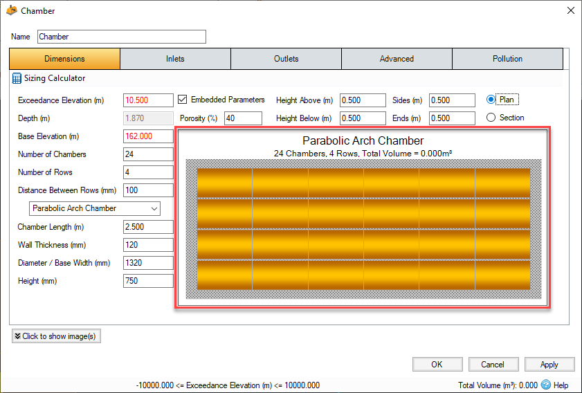
The preview box shows the user a top down view of the chamber drainage system, including the buffer space (if any). This box will display when the minimum amount of information is entered by the user: at least Chamber Length and Width.
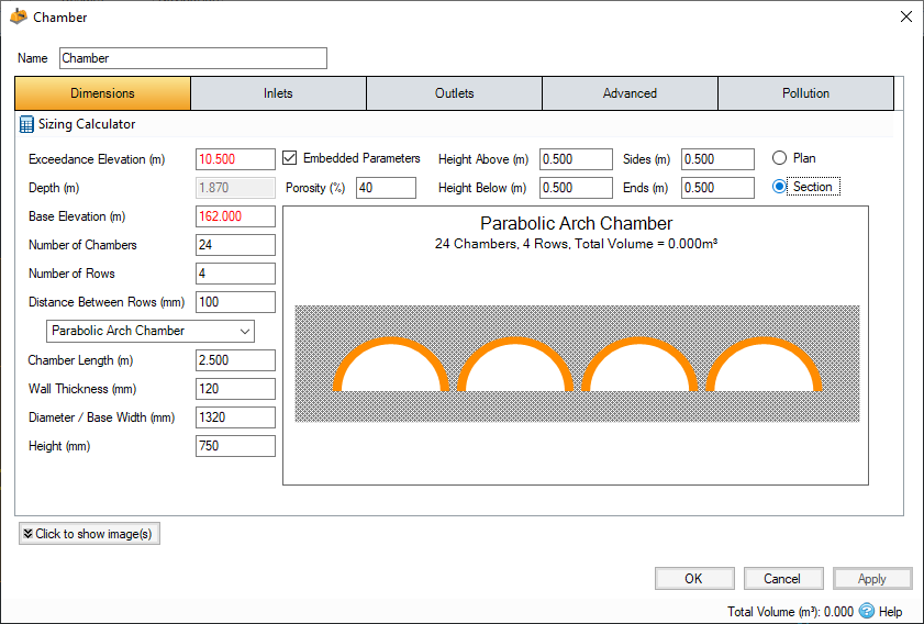
The radio buttons to the top right allow switching between the top down plan view, and the end-on section view showing the cross sections of the chambers. The title gives a strong 'at a glance' look at the structure, showing the Chamber name, number of chambers and rows, as well as the total retention volume (including embedded, if enabled).
Sizing Calculator

The Sizing Calculator option allows the user to re-size the Chamber by specifying a volume and a parameter to modify to achieve the desired volume. The Sizing Calculator is discussed in more detail in the Stormwater Control Sizing Calculator section.
The number of rows is never changed when using the Sizing calculator. Please note that with large values of Distance Between Rows or Sides/Ends embedded, the sizing can be quite sensitive to the number of rows.
Inlets
Explore the Inlets page for more details on the different types of Inlets that can be specified.
Outlets
Explore the Outlets page for more details on the different types of Outlets that can be specified.
Advanced
The Advanced tab has the following fields:
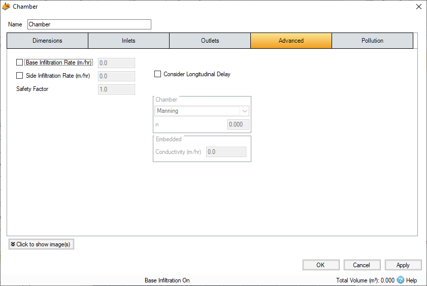
Base Infiltration Rate - Defines the rate of infiltration through the base of the structure. If Embedded options are disabled, the footprints of all the individual chambers are used instead of the SWC base dimensions.
Side Infiltration Rate - Defines the rate of infiltration through the sides of the structure. This should be determined from a performance site test. This option is only available if Embedded options are enabled, and only applies to the sides of the Embedded structure.
Safety Factor - Reduces the infiltration rate during the analysis to account for silting up or poor maintenance. This is required for the UK.
Consider Longitudinal Delay - Determines if a time of travel needs to be considered across the structure. This may not be required as they are laid flat and can be considered as filling instantaneously. If the travel time is to be considered a roughness method and value should be selected.
Friction Scheme - This applies to the chamber itself. Specifies the formula used to calculate velocity and time of travel. Select from: Manning's, and Colebrook-White. The variable below the combo box depends on the option selected.
n - Manning’s n roughness value. Used by the Manning Formula equation to calculate the velocity and therefore time of travel when using the Manning's option.
Roughness - Colebrook-White roughness value. Used by the Colebrook-White Formula equation to calculate the velocity and therefore time of travel when using the Colebrook-White option.
Conductivity - This applies to the fill material defined by the embedded parameters. The conductivity rate is used for the calculation of both the horizontal and vertical transfer of the water in the sub-surface layers. Please refer to Guidance on Conductivity Rates for guidance on how to set these values depending on the type of material.
Pollution
The Pollution tab has the following fields:
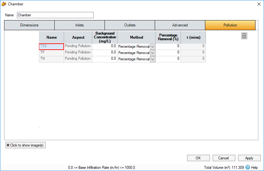
Name - Name of pollutants. This is populated based on the Pollutants set up as part of the Site Data.
Background Concentration - Value below which the pollution concentration cannot fall during analysis. When concentration reaches this elevation, no further removal occurs.
Method - Percentage Removal or First Order Decay method can be chosen. Click on the links for more information about each method.
Percentage Removal - Available if Percentage Removal entered. The value entered will be deducted from the Inflow into the system.
τ - The decay time constant or (mean) lifetime of the pollutant. It can be entered manually or calculated from the decay constant or decay half-life. See Pollutant Removal Method - First Order Decay for more details.