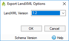
Export Pipe Network(s) allows the Connections and Junctions within the current phase to be exported to a LandXML file so that they can be shared with other applications, such as Autodesk® AutoCAD® Civil 3D®. Select the option and specify a location and name for the XML file, this will then present the Export Options as below.
Export Options
When exporting a LandXML file there are a couple of parameters that need to be specified.

LandXML Version
This is the version of the LandXML Schema that the export should support. The differences are small and most applications now support version 1.2. However some older applications, or versions of, may only support the older versions so they are available as an option.
Nominal Pipe Size
This is the size of pipe that will be used to represent any conceptual connections that may be present in the InfoDrainage design. i.e. No Delay, Lagged Flow and Custom Connection. This can be set to match the application you are importing into. For example the smallest part in your Civil 3D Parts List.
Annotations
Any visible annotations in InfoDrainage will be added to the Description attribute of the exported pipe network item.
Handling unsupported data
InfoDrainage contains some information that is not supported by the LandXML file format. As such they are either approximated as best as we can within the LandXML file exported. These are:
Stormwater Controls
- These are not supported by LandXML so a simple structure (i.e. node with no volume) is provided at these locations with a label explaining what they are.
- In addition to the Stormwater Control itself the Inlet and Outlet attachment points show on Plan can not be represented. To maintain the layout the export will contain a 'connection', or null, structure for each of the inlet and outlet locations. Connections (pipes) will then to/from these locations.
Connections
- Number of Barrels – If a value of more than 1 is specified the export will contain multiple versions of the same pipe/channel with the name postfixed with _X_Ø, where X is the number of the barrel.
- Colebrook-White roughness - this is not supported by LandXML so a Mannings n of 0 will be exported instead.
- Triangular Channels – These will be exported as an equivalent ‘v’ shaped channel.
- Conceptual Connections (No Delay, Simple Time Delay and Lagged Flow) – These will be saved as a Circular Pipe with a nominal diameter, as specified on the Export Options.
The curve coordinate is placed in connection center property in the LandXML file to preserve it.