Items can be created by importing features from GIS data files.
Currently supported formats are:
- Shapefile (.SHP)
- File Geodatabase (.GDB)
GIS features supported and what they can be used to create
| Feature Class | Objects Created |
| Point | Junctions, Inflows |
| Polyline | Connections |
| Polygon | Inflows, Stormwater Controls - SWC Land Uses, Soil Types |
Step-by-step guide
There is a wizard to guide the user through the GIS feature import process. The wizard is a user interface that presents a user with a sequence of dialog boxes that lead the user through a series of well-defined steps. To progress through the steps in the wizard, press the Next button. To return to a previously completed step, press the Previous button.
You can use the Tree View to start the wizard. Right Click on the type of object that is to be imported and select 'Import from GIS'.
- File Selection

This step allows you to specify the type of GIS file being loaded and to locate the file/folder by pressing the Select button.
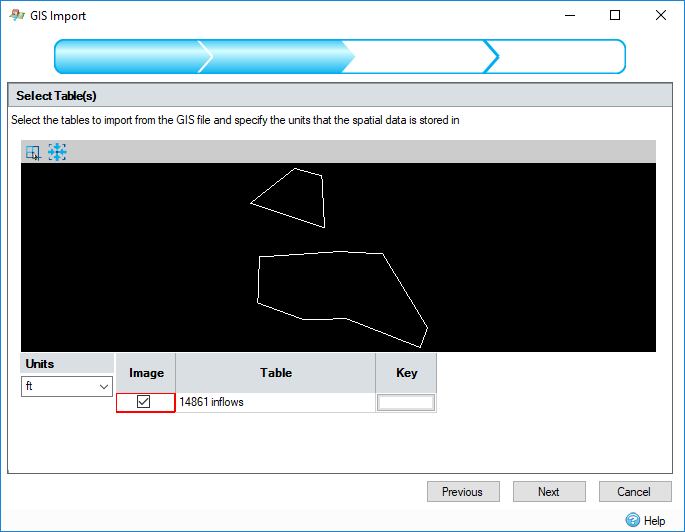
- Table Selection

The GIS data source may contain a number of tables. This step displays a preview of the data in the tables and other options. Features with more than 1000 vertices will not be imported.
Units - Select the units that the GIS data being loaded is in so that it can be converted for use with the current Unit Selection within the software.
Tables Spreadsheet
Image -The preview pane displays data from the currently selected tables. Tick the check box to toggle the selection of the table's data. At least one table must be selected, so if the data source contains only one table the check box will be disabled.
Table - Displays the name of the table.
Key - Click the button to change the color of the table's data in the preview pane.
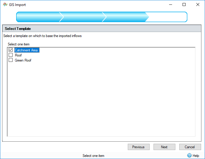
- Template Selection

This step displays a list of Object Templates that can be used to build objects from the imported data. These templates can be the predefined types or user created. The selected template will be used to build the objects for the imported features.
This step is performed twice when importing connections. The first time to select the default connection type and the second time to select a junction type to be created at connection endpoints where objects do not currently exist in the current stage design. The connection or junction type to create may be overruled depending on attribute values that are imported from the GIS data tables, see info below.
This step is not performed for Soil Types. Soil Types do not have object templates.
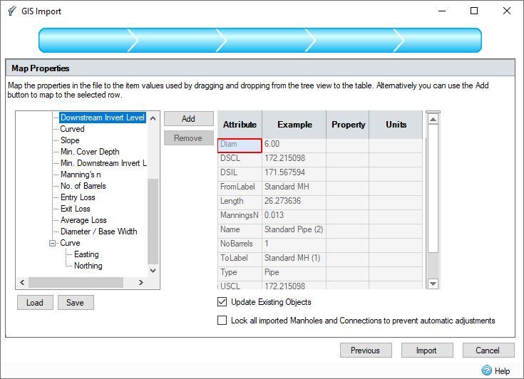
- Property Association

The geographic features imported may have associated nonspatial information called attributes. These attributes can be imported with the feature and assigned to properties of the created object. For example, a collection of manholes may be imported with their names and depth assigned from the attribute table.
This step shows a control that allows the attributes in the selected GIS tables to be mapped or assigned to properties in the object created from the selected template. The left hand side of the control shows a tree view of the properties in the object that will be created. The right hand side of the control shows a table of attributes in the GIS tables with an example of the data that would be imported.
To make an association, a property can be dragged from the properties tree view and dropped in the property column of the attribute grid. Alternatively, highlight the required row and tree node and press the 'Add' button. To remove an association, highlight the attribute row and press the 'Remove' button.
When an association has been made, if the property selected has Unit Selection, the units column in the attribute table will be populated with a combo box, containing possible units for the attribute values. On import, the attribute values will be converted from this unit to the currently selected unit in the software.
The current association configuration can be saved by pressing the 'Save' button and a previously saved configuration can be loaded by pressing the 'Load' button.
If the Update Existing Objects option is checked, the import will check for items with the same names and types to update rather than create. All internal information on the duplicated objects will be updated to match the selected imported attributes. If no suitable item to update can be found, it will be created as usual.
If the Lock all imported Manholes and Connections to prevent automatic adjustments option is checked, the import will set each manhole and connection to have their elevations locked using the Lock state.
-
Map Unavailable Values (Land Uses and Soil Types only)
If any of the following attributes have been assigned, additional pages may be displayed in the wizard:
Land Uses: Land Use, Cover Type, Condition
Soil Types: Soil Group
InfoDrainage will attempt to assign the attribute values read from the GIS file to the available InfoDrainage property options for the imported features. If no suitable mapping is discovered for one or more of the GIS attribute values, a further mapping page will be displayed that will allow an association to be made.

- Import Summary
At the final step on the wizard, pressing the Import button will perform the import and create the InfoDrainage objects. When this operation is complete, the Import Summary form will be shown where a summary of the objects created during the import.
Inflow Specific Information
- If a junction or part of a stormwater control exists within the outline of the imported inflow, the inflow will be connected to that node. If there are multiple nodes that can be connected to, the first that was added to the phase will be selected.
- If To is imported, and an existing junction or stormwater control exists with that name, the inflow will be connected to that node. This overrides the automatic connection rules.
Junction Specific Information
- If Cover Elevation, Invert Elevation, Depth, Length, Diameter or Width are imported a Manhole will be created.
- If Length or Width are imported, the manhole created will be rectangular.
- For a rectangular manhole, if width is imported and length is not, an imported diameter will be used to assign the length value
Connection Specific Information
- If Diameter, Height and Side slope are imported, a trapezoidal channel will be created.
- If Diameter, Height but not Side slope are imported, a rectangular channel will be created.
- If Height and Side slope but not Diameter are imported, a triangular channel will be created.
- If From or To are imported, and an existing junction or stormwater control exists with that name, the connection will connect to that object and the spatial coordinates will not be used.
If you see a message that says that genuine Autodesk software is required, the GISDataProvider component has been tampered with or is corrupted. To resolve this, repair the installation by going to Add and Remove Programs.