The Import option allows one, or more, Phases from within an InfoDrainage design to be imported into the Civil 3D® design.
This will create a Pipe Network for each phase imported that will contain the Closed sections and Manholes. Where it is not possible to represent elements within the InfoDrainage design within the Pipe Network, i.e. open channels, or Stormwater controls, they will be created as alternative entities. Please see Representation of Unsupported Data for more information.
Import Wizard
There is a wizard to guide the user through the import process. The wizard presents the user with a sequence of dialog boxes that lead the user through a series of well-defined steps. To progress through the steps in the wizard, press the Next button. To return to a previously completed step, press the Previous button.
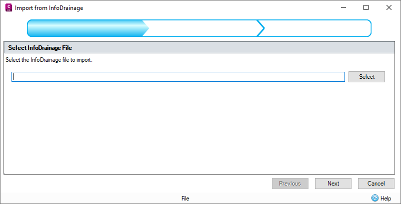
Step 1: File Selection
This step allows the selection of the file to be imported from. Pressing the select button invokes a file selection dialog to allow easy location of the file/folder.
Only InfoDrainage files from the currently installed version or previous versions can be loaded. An attempt to load an InfoDrainage file from a newer version will result in a warning message.
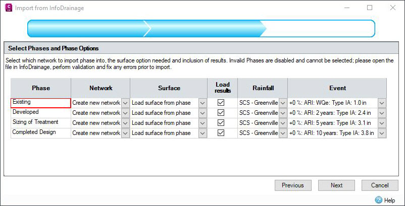
Step 2: Phase, Surface, and Results Migration
This step allows the selection of phases and surfaces that will be imported from InfoDrainage. Each selected phase will be imported as a Pipe Network in the Civil 3D design based on the chosen network.
Network
There are multiple network import options that can be selected on the Part Mapping Manager during the import from InfoDrainage.
Create New Network - A new network will be created for the specified phase. If the phase has previously been imported into the drawing this option will not be available.
Do Not Import - This Phase will not be imported. (Note if the phase isn't valid this option is hard set)
A Selection of Networks in the Drawing - Each network found in the drawing is listed, if selected the phase will be imported into the chosen network. If the phase has previously been imported into the drawing, only the network it was imported into will be listed. Networks referenced from external source drawings are not available to import into.
Surface
There are three surface import options that can be selected on the Part Mapping Manager during the import from InfoDrainage.
Use Existing Civil 3D surface - The existing network surface will be used. The import will not modify the surface.
Create Surface from Cover Elevations - A surface will be created for the network using the InfoDrainage junction location and cover elevations as well as stormwater control outlines and exceedance elevations.
Load Surface from Phase - A surface will be created from the InfoDrainage phase surface vertices and breaklines.
Load results
This option will only be available if valid analysis results and rainfall data have been detected.
Selecting the Load results option will load the analysis results generated from InfoDrainage. This is essential for the loading of the Hydraulic properties for structures and pipes in Civil 3D. The values will be loaded based on the rainfall and event selected during this step.
The selected storm is displayed in the Extended Properties Data for the items that have Hydraulic Grade Line (HGL) and Energy Grade Line (EGL) loaded in from the analysis results. For pipes, the Maximum Velocity is also displayed.
To calculate the energy grade lines, the application goes through all of the incoming and outgoing connections for the node, finding the largest Maximum Velocity. That value is then used to calculate the EGL for the particular node.
For pipes, the Return Period of the selected event and the Flow Rate of the connection are displayed in the Pipe Properties for each of the imported connections.
For InfoDrainage connections with multiple barrels, the Maximum Velocity and the Flow Rate for each barrel in Civil3D is equal to the value from the InfoDrainage connection divided by the number of barrels in the connection.
Step(s) 3 till end: Parts Mapping
For each selected phase there will be a parts mapping step, which allows the mapping of InfoDrainage types to Civil 3D part types. See Parts Mapping for more details.
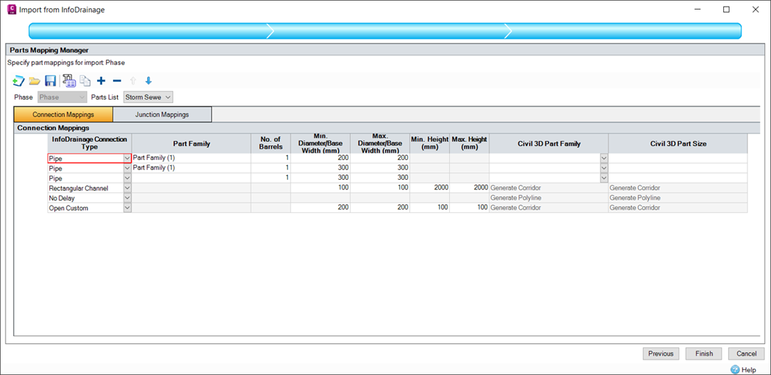
When the step is initially shown, the phase to import is examined. If any network parts are discovered that have no current mappings, a blank entry will be added for that part type.
When Next or Finish is pressed at each parts mapping step the given parts mappings will be validated. Any invalid properties will be flagged and will need correcting before the step can be completed.
Import Warnings
The following table lists some common Import Warnings you may encounter when importing a InfoDrainage file.
| Warning |
| "Connection has vertical sides which is not supported in Civil 3D. The top Area has been increased slightly to avoid this. " |
| "Stormwater Control has an overhang which is not supported in Civil 3D. The data has been capped where the Area increases with depth after decreasing with depth. " |
| "Stormwater Control has vertical sides which is not supported in Civil 3D. The top Area has been increased slightly to avoid this. " |
| "Duplicate name detected original name has been changed to new name " |
| "The number of barrels specified means that pipes do not all fit inside the manhole. Pipes have been overlaid to maintain connectivity but a larger manhole may be needed. " |
Removal of Items
If an InfoDrainage phase is re-imported, it will replace the previously imported network.
Any items that were deleted from the InfoDrainage phase since the previous import and any items added to the Civil3D® design since the previous export will be shown on the warnings form.
The user can select whether to delete old InfoDrainage data and/or the new Civil3D® data by ticking the appropriate boxes underneath the warnings grid.