The Parts Mapping Manager form allows you to define mappings between InfoDrainage and Civil 3D® parts.
There are two tabs, one for the definition of connection mappings and the other for junctions.
Exclusive to the Part Mapping Manager is a toggle that will swap the current part mapping to either the import mappings taken from the InfoDrainage file or the export mappings which will be taken from the current Civil 3D®networks.
Also exclusive to the Part Mapping Manager is a checkbox to allow the viewing of hidden Part Mappings. Part Mappings will be hidden if you have removed an object that previously had a mapping from the InfoDrainage file or the Civil 3D® network as this mapping no longer applies to your current mappings. When the object is added back the mapping is restored with all the information entered previously. By checking this box you can view the mappings that are hidden in order to make changes to them or remove them completely.
Toolbar Buttons
New
Discard the current mappings. If there are current mappings the user will be given the option to save them before they are cleared.
Open
Allow a mapping configuration to be loaded from an external file. If there are current mappings the user will be given the option to save them before the new file is loaded. This can be an InfoDrainage for Civil 3D® mappings file (.IDCPX) or a MicroDrainage parts mappings file (.PMX). For further information on which MicroDrainage connection types are supported in InfoDrainage see MDX File Format.
Save
Save the current mapping configuration to an external file.
Populate Mappings
Loops through the selected InfoDrainage phase and finds any mapping that has not currently been filled out in the Parts Mappings Manager and adds a new entry for this mapping.
This works for import by looking at the current phase being imported and finds every object in the phase and compares to the mappings currently filled out, adding any that are not found in the mappings. Import exclusively has the part family column that is populated in InfoDrainage, which is also used in the mapping process. A new mapping is created if there are any differences in the following columns: object type, part family, no of barrels and diameter/height + width. For export the same thing happens but the Civil 3D® networks are looped over instead.
Duplicate Mapping
Add a new row beneath the currently selected row and duplicate the contents of the currently selected row onto that new row.
Add Mapping
Add a new row to the mapping grid.
Remove Mapping
Remove the currently selected row from the mapping grid.
Priority
During an import the mappings list will be searched for a matching mapping. The search will start at the top of the list and will stop when a match is found. The mapping priorities can be adjusted using the increase and decrease mapping priority buttons.
Grids
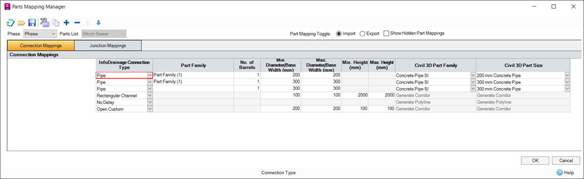
On each tab there is a grid. During import the left hand columns of the grid allow the definition of the InfoDrainage item by specifying the type and various property limits. The two right hand columns allow the specification of the matching Civil 3D® part family and part size. During an export the Civil 3D® part columns are on the left of the grid and the desired dimensions for the exported InfoDrainage part are specified on the right.
When the form opens the grid will populate itself following the same logic as the Populate Mappings button.
Import Specific
For conceptual connections the Civil 3D® columns will be locked as a polyline will be created for these connection types.
The Civil 3D® columns are also locked for channels and open custom connections, as a corridor will be created for these connection types.
The Civil 3D® columns are also locked on the Junctions tab for simple junctions where null structures will be created.