Inflows, Junctions, Stormwater Controls, Connections, Land Uses, Soil Types, Surface Data, and Background Data can all be loaded from CAD Files via the Load CAD Wizard.
Areas for Inflows, Stormwater Controls, Land Uses and Soil Types require polygons to be imported.
Junctions require points, circles, ellipsis or rectangular polygons to be imported. For manholes, the imported junction will have a circular chamber unless the import is from a rectangular polygon when it will have a rectangular chamber.
Connections require lines, polylines, or circular arcs to be imported.
Loading pipe network(s) from CAD requires both junctions and connections to be imported.
Currently supported file formats are:
- Drawing eXchange Format (.DXF)
- AutoCAD Drawing (.DWG)
Select Source
This step allows the location of the file to be loaded by pressing the select button.
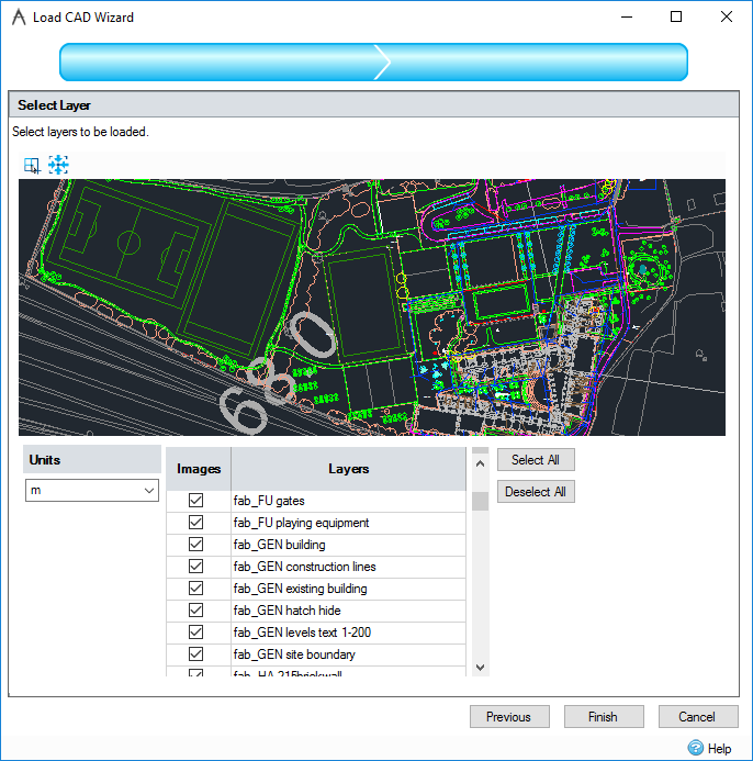
Select Layer
This step allows layers of the CAD file to be turned off before loading, as well as setting the units of the file, providing a preview image of the file, and additional options when loading surface data.

Toolbar
At the top of the page is a toolbar containing controls for the preview image.
Band Zoom: Clicking this icon lets users zoom into a specified area of the drawing using the Band Zoom tool.
View Extents: Zooms out the viewing window to full size extents.
Preview Image
The preview image will display the layers of the CAD file which are selected in the layers grid. The view can be moved by clicking and dragging with either the left or middle mouse button. The view can be zoomed in and out with the scroll wheel. The size of the preview image can be changed by left clicking and dragging the bottom edge.
Units
Select the units for the DXF/DWG being loaded so that it can be converted for use with the current units within the software.
Cover Type
This section appears only when surface data is being loaded. Surface Data is added to existing ground points and breaklines.
Points Only:
-
3D lines become two ground points, one at each end of the line.
-
3D points become one ground point at the 3D point coordinate.
-
3D circles become a single ground point at the center of the original circle.
-
3D Arcs are approximated to a collection of points based on the total angle the arc passes through. Each point has assumed its elevation (Z) from the center of the ellipse/circle it is based on.
Include Breaklines:
-
3D lines are loaded in as a Breakline. This means that when the ground model is triangulated none of the triangles will cross this line.
-
Points and circles are both loaded in as individual ground points.
-
3D Arcs are approximated to a collection of breaklines based on the total angle the arc passes through. Each point has assumes its elevation (Z) from the center of the ellipse/circle it is based on.
Text to Cover: The program can also convert text entities to surface points if this option is turned on. The surface point will exist at the text insertion point and will have an elevation equal to the value of the text object (the z coordinate of the text is ignored).
Layers Grid
The grid is used to select which layers are displayed in the preview image, and therefore brought in to the design after clicking Finish.
Areas / Images / Surface Data: This is the first column of the grid. The header of this column is dependant on what the CAD file is being loaded into. The check boxes in this column determine if a layer will appear in the preview image loading.
Layers: The names of the layers in the CAD file.
If importing a CAD file previously exported from InfoDrainage, you may see a layer titled XPS_StormwaterControlChambers. This layer contains all of the internal Chamber sub-outlines, and should not be used to import Stormwater Controls or Inflows. The full outlines of all Stormwater Controls are contained in the XPS_StormwaterControl layer.
Select / Deselect All
Clicking on the Select All button will select all of the layers in the table and conversely Deselect All will un-check them.
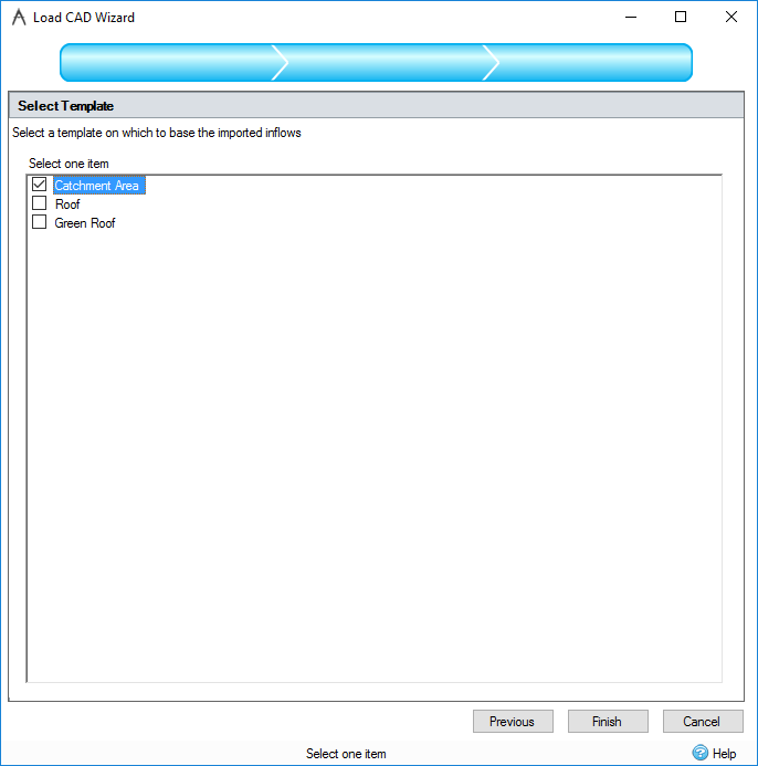
Select Template
When using the Load CAD Wizard to load areas of either stormwater controls, inflows, or Land Uses, a third step will appear in the wizard. This step allows the selection of a template which the imported areas will be based on.
When loading junctions the third step in the wizard will allow the selection of a template to base the imported junctions on.
When loading connections the third step in the wizard will allow the selection of a template to base the imported connections on. A fourth step will allow the selection of a template to base the junctions created to support connection endpoints on.
When loading pipe network(s) there will be steps for selecting both the junction and connection type to base imported items on.
When loading Soil Types, this section is skipped. Soil Types do not have object templates.

For a Sanitary phase importing Stormwater Control is not available.
After Loading
Viewing the Data:
Once loaded the CAD File(s) will be shown in the Tree View under the CAD Data node. The file/layer name is shown to make each file distinguishable. Under that will be a list of each layer loaded from that source. It is possible to adjust the visibility of each layer using the checkbox next to the layer name.
It is also possible to adjust the visibility of the all of the CAD Data at once using its checkbox. This will have the effect of turning on/off all of the CAD files as one for ease.
Deleting the Data:
It is possible to remove all CAD File references by Right-Clicking on the 'CAD Data' node on the Tree View and selecting 'Clear All'.
Alternatively, each CAD file/layer can be removed individually by Right-Clicking on the Files node on the Tree View and selecting 'Clear'.
Refreshing Data:
CAD Entity data is not stored to the .iddx file directly, instead a link to the CAD file(s) is maintained so that they can be reloaded each time. As such the data shown by InfoDrainage will be as up to date as the CAD file was when the .iddx was loaded. If a CAD file is not present when the .iddx is loaded a warning will be displayed and the file removed, but the file can be re added later if needed.
However, it is possible that a CAD file may be updated while you are using the software and you may wish to reload that updated CAD Data. This can be done by Right-Clicking on the Files node on the Tree View and selecting 'Refresh'.
Displaying an imported CAD file in Windows Explorer:
The location of an imported CAD file can be displayed by selecting the file's node under the CAD Data node in the Tree View, right-mouse clicking to show its menu and selecting Open Containing Folder.
Converting Imported Polygons to Areas
Imported polygons can be converted to inflow, stormwater control, land use, or soil type areas. Right click the item on the tree view and select the appropriate 'Convert To' menu item. If more than one template of the item type chosen exists, you will be required to select a template from the template picker before the items will be created and displayed on the plan. Only polygons will be converted, points and lines will be ignored. If no polygons are found in the selected layer(s), a warning message box will be displayed to inform the use that no areas were selected.