| File/s needed: |
|
Click to download the Metric Tutorial Model files. Note: These model files contain specific items for Civil 3D®, which are not present in the other chapters. |
The workflow in this tutorial will start with a pipe network in Civil 3D, which will be imported to InfoDrainage for pipe design and simulation. Once work has been completed in InfoDrainage, you will then export the network back to Civil 3D.
To complete this tutorial, you will require "InfoDrainage for Civil 3D " installed. Note that:
- If you have installed InfoDrainage using the Innovyze system, this plugin for Civil 3D must be installed separately. You can download the plugin from the InfoDrainage download page on the Innovyze Support Portal.
- If you have installed InfoDrainage using the Autodesk system, this plugin is installed as part of the Ultimate installer by default (provided that you have Civil 3D on your machine), so no additional actions needed for this case. If it is not installed, you can download the plugin from the Autodesk Desktop Application (ADA).
Exporting from CAD to InfoDrainage
-
Open the file Initial CAD Import.dwg in Civil 3D.
Note: Ensure that you have the InfoDrainage ribbon in Civil3D (screenshot below), if not follow Installing InfoDrainage for Civil 3D®.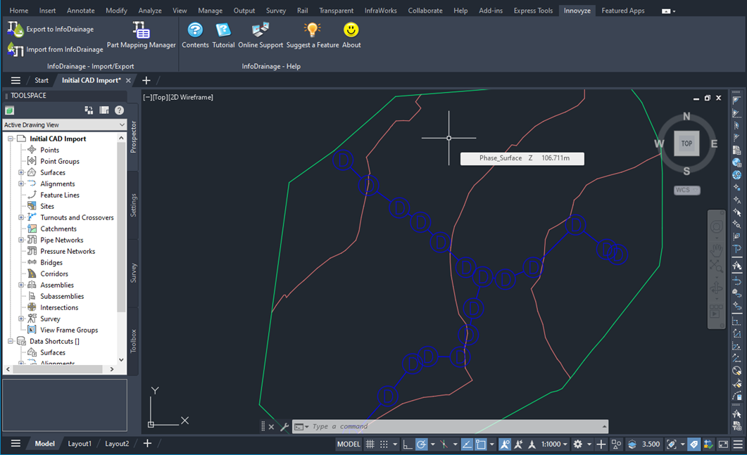
- Select
Export to InfoDrainage on the ribbon.

- Press
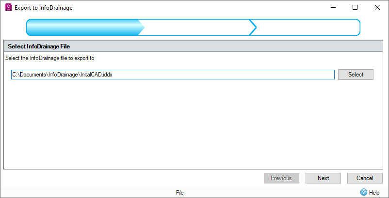
Select to set a save location and name of the InfoDrainage file for the pipe network that will be imported. Click
Next.
-
On the phase selector, ensure that the Network and Phase check box are selected. Using the drop-down menu, select Do not export a surface. We will import the surface later in InfoDrainage.
Note: Note that if you had a surface loaded into your drawing, you could export it with the pipe network by selecting it on the drop-down menu. Alternatively, you select generate a surface from the cover elevations if required.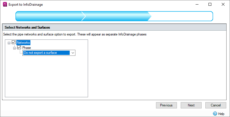
-
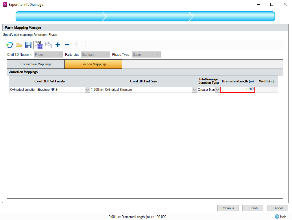
The final step is to assign part sizes in the Parts Mapping Manager. Here you will assign a pipe and manhole diameter manually that matches the part size in Civil 3D. Assign a pipe diameter of 100 mm and a manhole diameter of 1.2 m. In this case we only have one pipe and manhole size so the process is quite simple, in more complex networks with a range of sizes it will become more complex.
Note: The height or width columns would apply if you had a culvert conduit or a rectangular manhole, for this example we are just using a standard circular parts.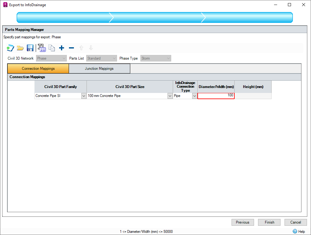
- Click Finish to export the network. It should only take a few seconds, but it would take longer if the network were larger.
- If you load InfoDrainage, you can then open the pipe network exported and complete the design work required.

For this example, we are going to skip ahead (in the next exercise) to the designed network and import it back into Civil 3D. At this point in InfoDrainage, you would import your CAD and/or surface if required and design the network to your specifications. Surface and CAD drawing are in the downloaded files if you wish to complete this step.
Importing from InfoDrainage to Civil 3D
In this example we have a designed network. From the exported network a pond, HydroBrake and inlet pipe have been added and all the pipes redesigned.
- Launch Civil 3D and select
Import from InfoDrainage.

- Select the file
Pond Design.iddx from the downloaded tutorial files.

-
Tick the phase you are importing. In this example on the drop-down menu, select Create surface from cover elevation.
Note: In a standard design you would likely be importing the pipe network with a surface loaded, in that case you could select Use existing Civil3D surface.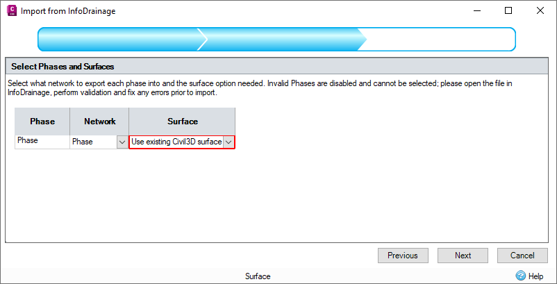
- The final step is to assign Civil 3D parts (like step 5 in the previous exercise). For this part, we will be using the Metric structure catalogue in Civil 3D but if you have your own/a different parts list feel free to use that applying the same principles.
- Set your Parts List from the drop-down menu on the top left. You will need to assign parts for each pipe diameter from your assigned parts list. First assign a Civil 3D Part Family
and then the Civil 3D Part Size. See below where we have assigned the concrete pipe family with the relevant pipe diameter.

-
Apply the same principles when applying parts for your manholes, set the part family and then relevant junction diameters.
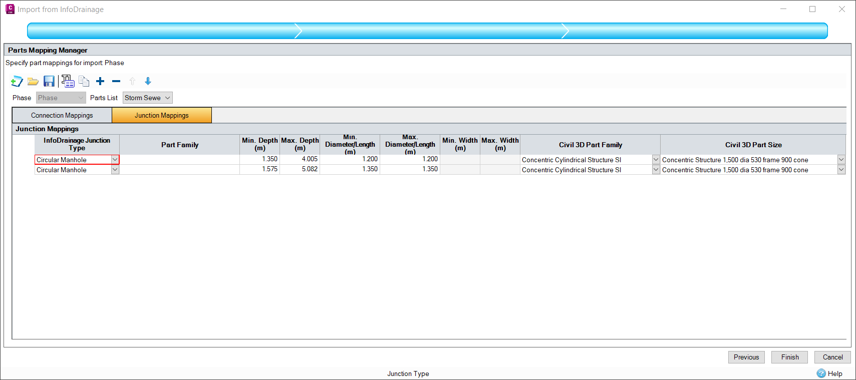 Note: Note that we did not have a 1350 mm in this parts list, so we used a 1200 mm as a placeholder.
 - Click Finish. The network will now export as a Civil 3D pipe network (leave the drawing open or save for the next exercise).
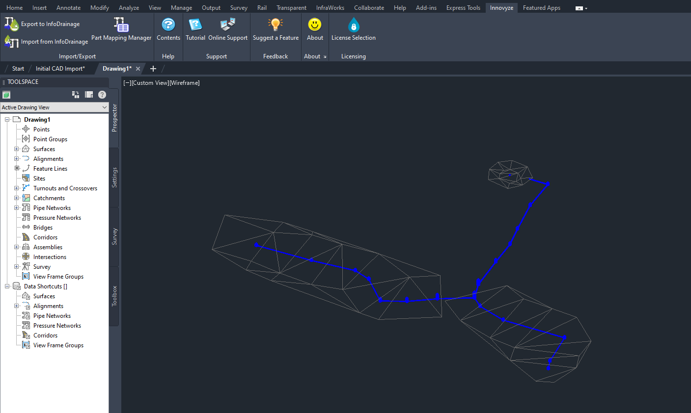

Updating a Civil 3D Network
If you make a change to your network hydraulically, you need to repeat the import/export process and re-run simulations. There are two workflows in this instance:
- Making a change to your network in Civil 3D – If you think the change will have an hydraulic impact on your network, you need to repeat the process outlined above to bring the network into InfoDrainage and run simulations. Minor changes such as moving a manhole a few meters can be excluded but use your own judgment.
- Making a change to your network in InfoDrainage and needing to push that change to Civil 3D – You just need to follow 'Importing from InfoDrainage to Civil 3D®'. If you are going to make a change that is hydraulically significant, we recommend following this workflow. The reason behind this is you can just push the update to Civil 3D after the change has been made rather than having to complete the import/export process twice. Another benefit is that part mappings already applied will be saved, which is shown in the exercise below.
In the activity below, we are going update the Civil 3D network after we have made a change in InfoDrainage (workflow two above). In this example, we have added a swale, this might be needed if you require more storage (perhaps additional contributing areas have been added). A few manholes have also been moved.
The starting point will be the end of the previous exercise. Quickly run through it again if it has been closed.
- (Optional) Open the network in InfoDrainage (filename ManholeMoveWithSwale.iddx) to see the changes made. A few manhole locations have changed, with a swale added parallel to the road NW of the site.
- Go to the Civil 3D network exported in the previous exercise.
- Follow the steps in 'Importing from InfoDrainage to Civil 3D' to import the InfoDrainage file
ManholeMoveWithSwale.iddx.

-
On the Part Mapping Manager step you should notice that all the parts are already mapped. This is as network is created as a revision the file in the previous exercise so all mappings applied previously will be saved (assuming the same parts list is applied). If you have to add a new pipe diameter, for example a 450 mm pipe, you will need to add this as a mapping.
Note: Note that the swale does not have a mapping assigned as when it is exported a corridor in the network will be generated. - Click
Finish. The network will now update with the changes.
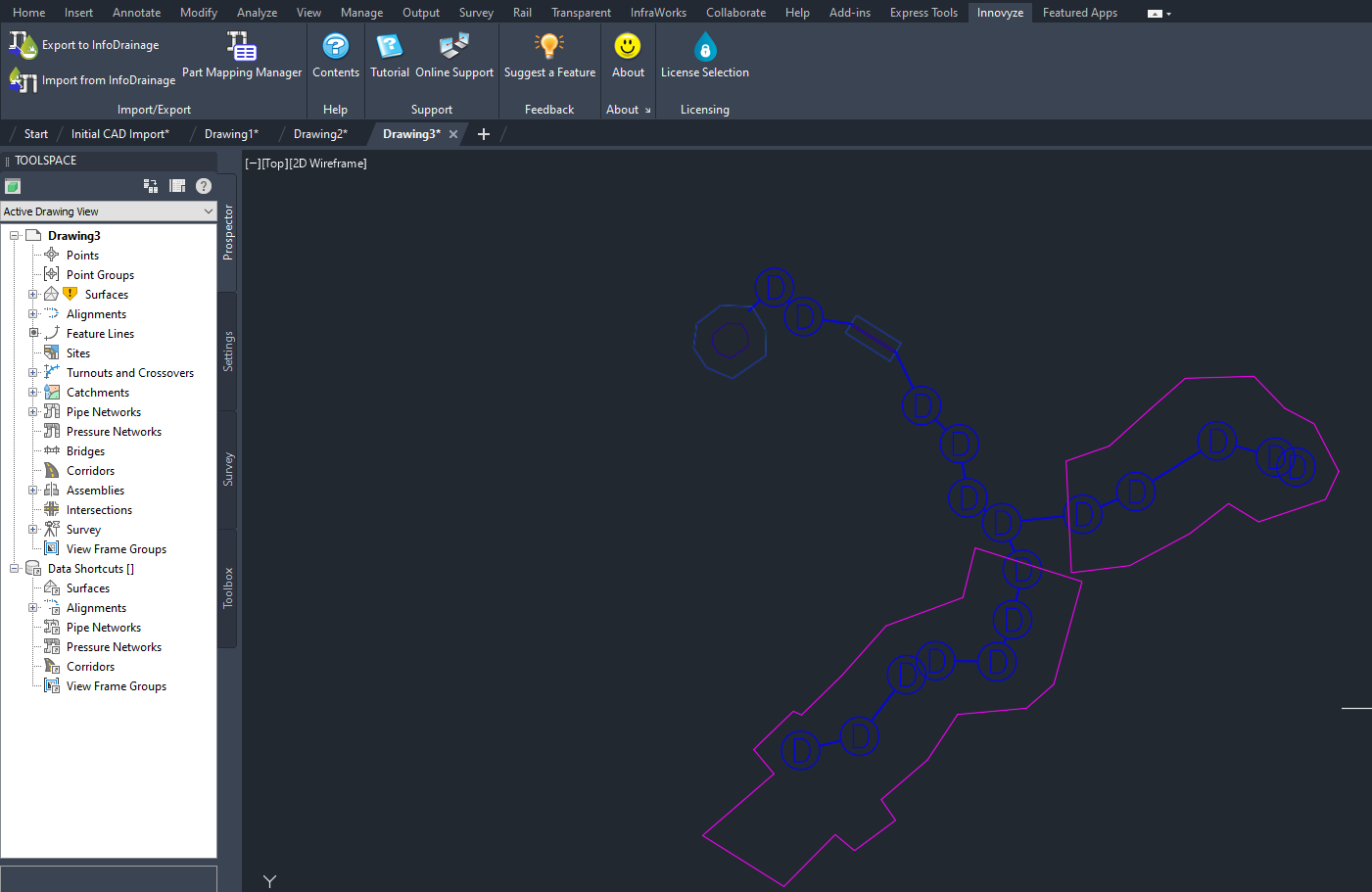
Saving Parts Lists
Saving parts lists can be done by clicking the Save Mapping button in the Parts Mapping Manager. This is useful if you will use the same parts on multiple projects, preventing you having to apply the same part each time. Another use is if you have company wide parts that you use, you could therefore have a company-wide parts list saved.
