The Network Design Report allows you to view a range of connection and Network Design data in a range of layouts. Once a flow path is selected from the first combo box, the report will display information dependent on the table layout. The table layout can be selected from a drop-down list on the combo box. The available table layout you can choose from are the following:
- Default
- Methode de Caquot
- Full
- HEC-22
- Sanitary Phases
The Network Design Criteria can be accessed via the toolbar, in order to change the flow and pipe restrictions without entering the Network Design Wizard.
If the Network Design Wizard has been modified, then the Recalculate Rational Results button can be used to update flow calculations without using the Network Design Wizard.
If the Maintain Refresh Rational Results toggle is on, the rational results will be automatically recalculated when the design is updated, the Network Design Criteria are updated, or a different flow path is selected..
The Audit button can be toggled to highlight potential errors with the current design. These include:
- Velocities outside of the limits set in the Network Design criteria. Shown only if the velocities have been set to be used within the criteria, and the values given for the max and min are valid.
- Flow exceeding capacity.
- Minimum cover depth not met. Shown only if the minimum cover depth option is selected in the network design criteria.
Default
A layout similar to the Network Design Results of previous versions.
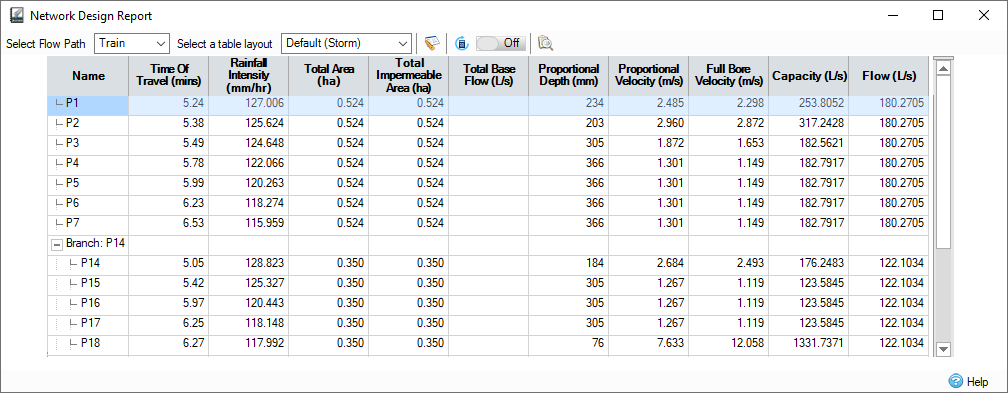
Name - Name of the connection as shown on the plan view.
Time of Travel - The Travel Time is calculated as the Min. Time of Entry from the Network Design + The Travel Time through the Upstream connections. The time of travel for a given connection is calculated using the velocity of flow under full bore conditions and the length of the connection.
Rainfall Intensity - The Rainfall Intensity is determined from the IDF data, specified on the Network Design , based on the Travel Time for the given connection. The Rainfall Intensity is then used in the selected Calculation Method to determine the flow used for Auto Sizing the pipes/channels.
Total Area - The total area (not factored by Runoff Coefficient) is used rather than the contributing area. This does not include the upstream contributing areas.
Total Impermeable Area - Total impermeable area from connected Inflows. This is factored by the Percentage Impervious specified per area before being summed.
Total Base Flow - Total base flow including all base flows from the upstream connections.
Proportional Depth - The Proportional Depth is the actual depth of water in the pipe for the calculated flow.
Proportional Velocity - The Proportional Velocity is the velocity of water in the pipeline (i.e. at the Proportional Depth) corresponding to the calculated flow.
Capacity Limited to XX% - The pipe capacity at the limited pipe conditions as specified in the Network DesignCriteria. The column is visible if Limit Pipe Full Conditions is ticked in the Network Design Criteria.
Full Bore Velocity - The Full Bore Velocity is calculated using either the Manning Formula or the Colebrook-White Formula and is based on full bore conditions.
Capacity - The Pipe Capacity is calculated using either the Manning's n or Colebrook-White equation and is based on full bore conditions.
Flow - The flow is determined based on the calculation method selected in the Network Design :
Rational Method : Flow = Rainfall Intensity x Total Area + Total Base Flow
(UK) Modified Rational Method: Flow = Rainfall Intensity x Total Area * Cr(1.3) + Total Base Flow
Methode de Caquot: Flow is calculated by a series of formula used by the Methode de Caquot.
The Default layout for sanitary phases has some differences, see Sanitary Phases.
Methode de Caquot
The default data set when the Methode de Caquot is selected as in the Network Design .
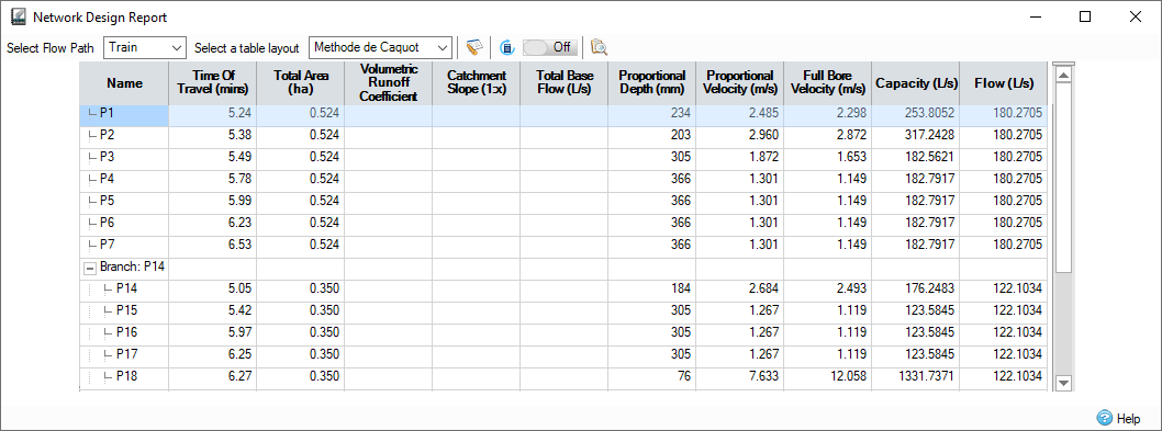
Name - Name of the connection as shown on the plan view.
Time of Travel - The Travel Time is calculated as the Min. Time of Entry from the Network Design + The Travel Time through the Upstream connections. The time of travel for a given connection is calculated using the Velocity of flow under full bore conditions and the length of the connection.
Total Area - When completing the Methode de Caquot method the total area (not factored by Runoff Coefficient) is used rather than the contributing area.
Volumetric Runoff Coefficient - This is the combined Runoff Coefficient determined by the Methode de Caquot calculations as the areas are combined.
Catchment Slope - This is the combined Catchment Slope that is determined by the Methode de Caquot calculations as the areas are combined.
Total Base Flow - Total base flow including all base flows from the upstream connections.
Proportional Depth - The Proportional Depth is the actual depth of water in the pipe for the calculated flow.
Proportional Velocity - The Proportional Velocity is the velocity of water in the pipeline (i.e. at the Proportional Depth) corresponding to the calculated flow.
Full Bore Velocity - The Full Bore Velocity is calculated using either the Manning Formula or the Colebrook-White Formula and is based on full bore conditions.
Capacity - The Pipe Capacity is calculated using either the Manning's n or Colebrook-White equation and is based on full bore conditions.
Flow - The flow is determined based on the calculation method selected in the Network Design:
Rational Method : Flow = Rainfall Intensity x Total Area + Total Base Flow
(UK) Modified Rational Method: Flow = Rainfall Intensity x Total Area * Cr(1.3) + Total Base Flow
Methode de Caquot: Flow is calculated by a series of formula used by the Methode de Caquot.
Full
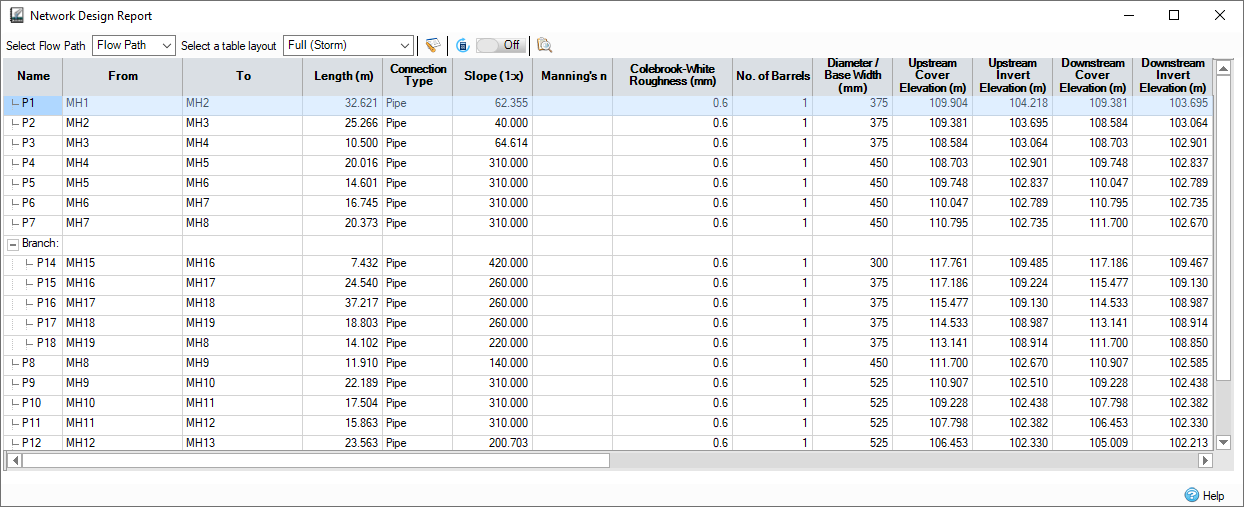
A more complete set of data, including many of the details entered during Network Design.
Hidden Columns
- No. of Barrels - To display this column, the flow path must include a pipe, box culvert or any channel.
- Height - To display this column, the flow path must include a box culvert or any channel.
- Manning's n - To display this column, the flow path must include a hydraulic connection with a Manning's n value.
- Colebrooke-White Roughness - To display this column, the flow path must include a hydraulic connection with a Colebrooke-White roughness value.
- Corner Splay - To display this column, the flow path must include a box culvert.
- Side Slope - To include this column, the flow path must include a Trapezoidal or Triangular Channel.
Name - Name of the connection as shown on the plan view.
From - The label of the item at the upstream end of the connection.
To - The label of the item at the downstream end of the connection.
Length - Length of the connection. If in red - the length was defined by the user, otherwise, it was calculated using the Connections coordinates from the plan view.
Connection Type - The types of connections are:
- No Delay - Imposes no effect of the movement of water.
- Lagged Flow - Introduces a time delay on the movement of water based on the Time of Travel value entered. Velocity and Time of Travel columns are shown by default.
- Pipe Connection - Allows a pipe, or series of parallel pipes, to be modelled with a Diameter, Longitudinal Slope, and Elevations. The dimensions can be entered as required or calculated using the Network Design calculation. Slope, Manning's n, Diameter/Base Width, Upstream Cover Elevation, Upstream Invert Elevation, Downstream Cover Elevation, and Downstream Invert Elevation columns are shown by default.
- Box Culvert - Allows a Box Culvert, or a series of parallel culverts, to be modelled with a Base Width, Height, Corner Splay, Longitudinal Slope and Elevations. The dimensions can be entered as required or calculated using the Network Design calculation. Slope, Manning’s N, Diameter/Base Width, Height, Upstream Cover Elevation, Upstream Invert Elevation, Downstream Cover Elevation, and Downstream Invert Elevation are shown by default.
- Rectangular Channel - Allows a Rectangular channel, or series of parallel channels, to be modelled with a Base Width, Height, Longitudinal Slope, and Elevations. The dimensions can be entered as required or calculated using the Network Design calculation. Slope, Manning's n, Diameter/Base Width, Height, Upstream Cover Elevation, Upstream Invert Elevation, Downstream Cover Elevation, and Downstream Invert Elevation columns are shown by default.
- Trapezoidal Channel - Allows a Trapezoidal channel, or series of parallel channels, to be modelled with a Base Width, Side Slope, Height, Longitudinal Slope, and Elevations. The dimensions can be entered as required or calculated using the Network Design calculation. Slope, Manning's n, Diameter/Base Width, Height, Side Slope, Upstream Cover Elevation, Upstream Invert Elevation, Downstream Cover Elevation and Downstream Invert Elevation columns are shown by default.
- Triangular Channel - Allows a non-symmetrical Triangular channel, or series of parallel channels, to be modelled with a Side Slope, Height, Longitudinal Slope, and Elevations. The dimensions can be entered as required or calculated using the Network Design calculation. Slope, Manning's n, Height, Side Slope, Upstream Cover Elevation, Upstream Invert Elevation, Downstream Cover Elevation, and Downstream Invert Elevation columns are shown by default.
-
Custom Connection - Allows a custom connection, or series of parallel connections, to be modelled with a Custom Cross Section, Longitudinal Slope and Elevations. The dimensions can be entered as required or calculated using the Network Design calculation. Slope, Manning's n, Upstream Cover Elevation, Upstream Invert Elevation, Downstream Cover Elevation, Downstream Invert Elevation, and the Cross Section columns are shown by default.
Slope - Longitudinal slope of the connection. This is calculated based on the Fall, between the upstream & downstream invert elevations, along the Length of the connection. Entering a value for the slope will therefore adjust the downstream invert elevation.
Manning's n - Manning's coefficient for the connection, which will be used in velocity and flow/capacity calculations.
Colebrook-White Roughness - Colebrook-White roughness for the connection, which will be used in velocity and flow/capacity calculations.
No. of Barrels - Number of barrels/channels laid in parallel.
Diameter/Base - Diameter of the connection if a Pipe, or base width of a Rectangular or Trapezoidal channel.
Height - Height of a Rectangular, Trapezoidal or Triangular channel.
Corner Splay - Introduced into a Box Culvert for pipe strengthening purposes. This value cannot be greater than half the current width or half the current height. The default value is 0 and will not be automatically adjusted.
Side Slope - Slope of the sides of a trapezoidal or triangular channel.
Upstream Cover Elevation - The cover/exceedance elevation at the upstream end of the connection. Elevations may be set automatically if sufficient data exists. See individual connection type pages for more details.
Upstream Invert Elevation - The invert elevation at the upstream end of the connection. Elevations may be set automatically if sufficient data exists. See individual connection type pages for more details.
Downstream Cover Elevation - The cover/exceedance elevation at the downstream end of the connection. Elevations may be set automatically if sufficient data exists. See individual connection type pages for more details.
Downstream Invert Elevation - The invert elevation at the downstream end of the connection. Elevations may be set automatically if sufficient data exists. See individual connection type pages for more details.
Cover Depth - For closed connections, the smaller of the upstream and downstream cover elevations.
Total Area - The total area (not factored by Runoff Coefficient) is used rather than the contributing area. This does NOT include the upstream contributing areas.
Total Impermeable Area - Total impermeable area from connected Inflows. This is factored by the Percentage Impervious specified per area before being summed.
Total Contributing Area - Total contributing area from connected Inflows . This is factored by the Runoff Coefficient and Percentage Impervious specified per area before being summed. This includes all the upstream contributing areas.
Volumetric Runoff Coefficient - The average (per unit area) preliminary sizing volumetric runoff coefficient of all inflows to the connection.
Local Time of Concentration - The time required for water to travel from the hydraulically most distant point of the drainage area to the inlet at the upstream end of the storm drain run under consideration.
Time of Travel - The Travel Time is calculated as the Min. Time of Entry from the Network Design criteria + The Travel Time through the Upstream connections. The time of travel for a given connection is calculated using the velocity of flow under full bore conditions and the length of the connection.
Rainfall Intensity - The Rainfall Intensity is determined from the IDF data, specified on the Network Design criteria, based on the Travel Time for the given connection. The Rainfall Intensity is then used in the selected Calculation Method to determine the Flow used for Auto Sizing the pipes/channels.
Total Base Flow - Total base flow including all base flows from the upstream connections.
Proportional Depth - The Proportional Depth is the actual depth of water in the pipe for the calculated flow.
Proportional Velocity - The Proportional Velocity is the velocity of water in the pipeline (i.e. at the Proportional Depth) corresponding to the calculated flow.
Capacity Limited to XX% - The pipe capacity at the limited pipe conditions as specified in the Network Design Criteria. The column is visible if Limit Pipe Full Conditions is ticked in the Network Design Criteria.
Full Bore Velocity - The Full Bore Velocity is calculated using either the Manning Formula or the Colebrook-White Formula and is based on full bore conditions.
Capacity - The Pipe Capacity is calculated using either the Manning's n or Colebrook-White equation and is based on full bore conditions.
Flow - The flow is determined based on the calculation method selected in the Network Design criteria:
Rational Method : Flow = Rainfall Intensity x Total Area + Total Base Flow
(UK) Modified Rational Method: Flow = Rainfall Intensity x Total Area * Cr(1.3) + Total Base Flow
Methode de Caquot: Flow is calculated by a series of formula used by the Methode de Caquot.
The Full layout for sanitary phases has some differences, see Sanitary Phases.
HEC-22
The layout used by Hydraulic Engineering Circular No. 22 for preliminary storm drain computation.
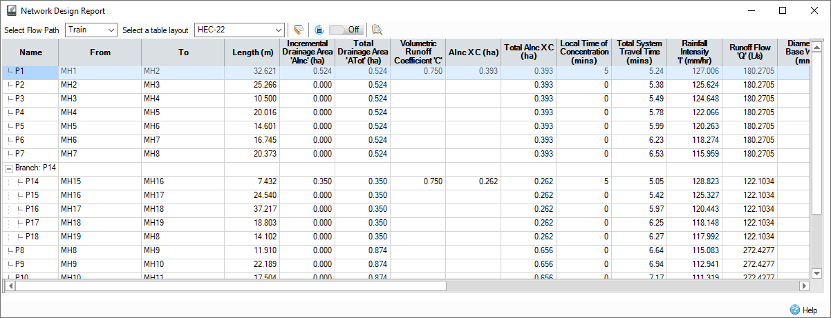
Name - Name of the connection as shown on the plan view.
From - The label of the item at the upstream end of the connection.
To - The label of the item at the downstream end of the connection.
Length - Length of the connection. If in red - the length was defined by the user, otherwise, it was calculated using the Connections coordinates from the plan view.
Incremental Drainage Area 'AInc' - Individual area from connected Inflows.
Total Drainage Area 'ATot' - Total area from connected Inflows. This includes all the upstream contributing areas.
Volumetric Runoff Coefficient 'C' - The runoff coefficient for the drainage area tributary to the inlet at the upstream end of the connection.
AInc X C - The incremental Drainage area multiplied by the runoff coefficient for the drainage area tributary to the inlet at the upstream end of the connection.
Total AInc X C - Total contributing area from connected Inflows. This is factored by the Runoff Coefficient specified per area before being summed. This includes all the upstream contributing areas.
Local Time of Concentration - The time required for water to travel from the hydraulically most distant point of the drainage area to the inlet at the upstream end of the storm drain run under consideration.
Total System Travel Time - The Travel Time is calculated as the Min. Time of Entry from the Network Design criteria + The Travel Time through the Upstream connections. The time of travel for a given connection is calculated using the Velocity of flow under full bore conditions and the length of the connection.
Rainfall Intensity 'I' - The Rainfall Intensity is determined from the IDF data, specified on the Network Design criteria, based on the Travel Time for the given connection. The Rainfall Intensity is then used in the selected Calculation Method to determine the Flow used for Auto Sizing the pipes/channels.
Runoff Flow 'Q' - The flow is determined based on the calculation method selected in the Network Design criteria:
Rational Method : Flow = Rainfall Intensity x Total Area + Total Base Flow
(UK) Modified Rational Method: Flow = Rainfall Intensity x Total Area * Cr(1.3) + Total Base Flow
Methode de Caquot: Flow is calculated by a series of formula used by the Methode de Caquot.
Diameter / Base Width - Diameter of the connection if a Pipe, or base width of a Rectangular or Trapezoidal channel.
Full Flow - The Full Flow is calculated using either the Manning's n or Colebrook-White equation and is based on full bore conditions.
Full Bore Velocity - The Full Bore Velocity is calculated using either the Manning Formula or the Colebrook-White Formula and is based on full bore conditions.
Design Velocity - The Design Velocity is the velocity of water in the pipeline (i.e. at the Proportional Depth) corresponding to the calculated flow.
Section Time - The travel time in the pipe section. Calculated by dividing length by the design velocity.
Upstream Invert Elevation - The invert elevation at the upstream end of the connection. Elevations may be set automatically if sufficient data exists. See individual connection type pages for more details.
Downstream Invert Elevation - The invert elevation at the downstream end of the connection. Elevations may be set automatically if sufficient data exists. See individual connection type pages for more details.
Crown Drop - Calculated by subtracting the downstream invert elevation of the previous connection from the upstream invert elevation of the current connection.
Slope - Longitudinal slope of the connection. This is calculated based on the Fall, between the upstream and downstream invert elevations, along the length of the connection. Entering a value for the slope will therefore adjust the downstream invert Elevation.
Sanitary Phases
For sanitary phases the default and full layouts differ to the storm layouts.
The following columns are not applicable: Time of Travel, Rainfall Intensity, Total Contributing Area and Total Impermeable Area.
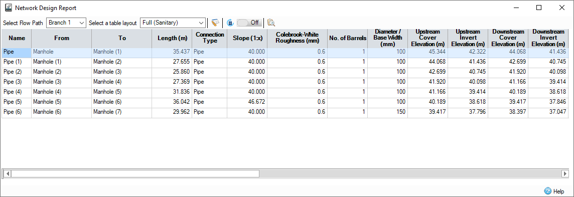
The reports contains the following additional columns.
Total Discharge Units - The total of all discharge units, see Sanitary.
Total Dwellings - The total number of dwellings, see Sanitary.
Proportional Velocity At 1/3 Flow - The proportional velocity achieved by a connection with only 1/3 of the calculated flow. The column is visible if Check Velocity is ticked in the Network Design Criteria and 1/3 Proportional Velocity or (UK) 1/3 Proportional Velocity is selected.