To add decorations to road and railway styles
Add vehicles, vegetation, or other 3D objects as decorations on any single track of a railway or any single lane of a road.
The style places 3D models relative to the centerline of the specified tracks or lanes. Tracks or lanes that have associated decoration definitions display that information in parentheses. Decorations are automatically adjusted to avoid intersections.
Click Manage
 Content
  (Style Palette).
Select the Road or Railway tab in the Style Palette.
Double-click the style to edit.
In the editor for the selected style, click
 .
.In the Decoration Editor, select the lane or track for the decorations.
For example, for a road style, you can place the decorations in various parts of the median, or in the bikeway, curb, green space, sidewalk, and so on.
Under Registered Decorations, click
 .
.In the Select 3D Model Style dialog box, select a type of decoration from the list.
For example, select 3D Model/Vehicles.
Click a model in the preview area and click OK. The model appears in the preview area of the editor.
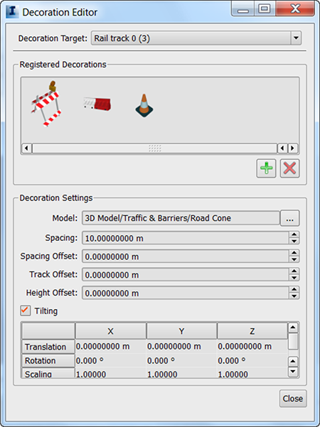
Specify the following:
Spacing: Specify the real-world distance between each occurrence of the 3D model.
Spacing Offset: Offset the first 3D model from the start point of a track or lane. Use this setting to control the spacing of multiple models along the same track or lane, for example, alternating streetlights and trees.
Use Spacing and Spacing Offset to distribute the 3D model along the track or lane.
Track Offset: Move the 3D model right by entering positive values; move it to the left by entering negative values.
Height Offset: Raise the 3D model by entering positive values; lower it by entering negative values. This setting is applied after the Track Offset.
Use Track Offset and Height Offset to adjust the model placement in track or lane coordinates.
Tilting: Causes decorations to follow the varying slope of the road or ground automatically, accordingly to the road curvature
Translation: Move the 3D model along its X, Y, and Z axes. Enter a positive or negative number for the X, Y, or Z axes. For example, to move the model to the right, enter a positive value for X.
Rotation: Orbit the 3D model along its X, Y, and Z axes.
Scaling: Enlarge or shrink the 3D model along the X, Y, and Z axes.
Use Translation, Scaling, and Rotation to transform the 3D model in its local coordinate system. These settings are also applied to the Transformation settings of the 3D model style.