To edit road styles
When modifying planning road styles, map the overall style to a Material Group. A material group applies materials for a combination of road shoulders, median strips, lane striping, and other components to a single road. Material groups can vary the road appearance when the feature passes through a tunnel or over a bridge.
Click Manage
 Content
  (Style Palette).
Display the style to edit.
- On the left side of the Style Palette, click the Road tab.
- Select the appropriate style catalog from the drop-down list.
Click
 to duplicate an existing style before editing it.
It is good practice to copy an existing style instead of changing the original version.
Double-click the new copy of the style to open the Style Editor window, or select the style and click
 .
.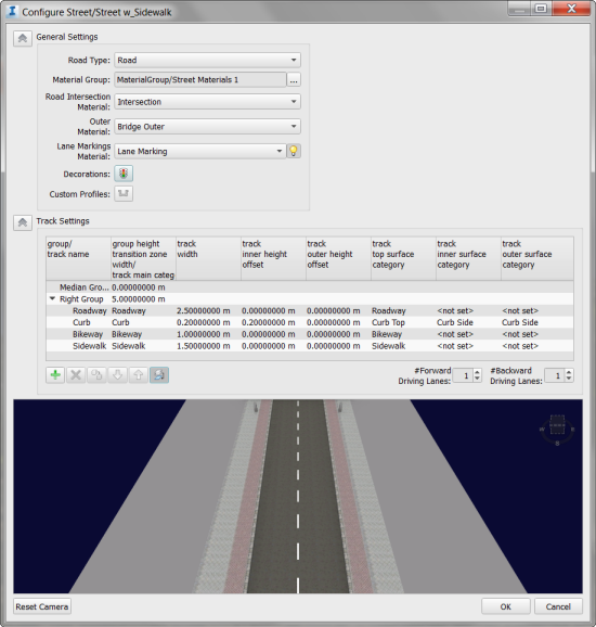
Under General Settings, specify the following:
Setting Description Road Type Select Road, Bridge, or Tunnel. Material Group The collection of materials and associated categories that map a material to the different parts of a road style. You can define each component of the material group separately, from within its catalog. See Edit Styles. Road Intersection Material Specify the category whose material will be used for areas where road segments cross. When road segments share a crossing region but use different road styles, the road segment with the highest Importance property determines the material for the crossing region. To set this property, display the Properties palette for the road segment. Under Transportation, enter a high value for Importance. Lane Markings Material Specify a category whose material will be used for lane markings. No lane markings are generated for intersection regions. Turn lane markings on or off using  .
.Decorations Click  and specify any decorations for this style.
Use the Track Settings section to define the road elements.
The rows in the Track Settings table represent elements of the road; the columns represent the attributes of each track. The rows are organized by groups: the right side of the road and the median strip.
By default, the left side of the road mirrors the right side.
- To create an asymmetric road, click (below the table). This adds a new group called Left Group. The new group appears at the top of the table.
- To add, remove, copy, or re-order tracks, use the buttons below the table.
- Double-click a table cell to edit it. Some cells contain a drop-down menu after you click in them.
Column Description Group/Track Name An identifier for this track and its group. The group is either Median, Right, or Left (if you added Left); the track is a component of one of those groups. Group Height Transition Zone Width/Track Main Category The Group Height Transition Zone Width applies to the group. The Track Main Category is the basic material type for the corresponding road element in the Track Name column. Options in the list are determined by the Material Group you selected in the General Settings area. Track Width Enter a width for the corresponding road element in the Track Name column. The default unit of measurement is used. Track Inner Height Offset Enter the beginning height of the corresponding road element in the Track Name column, relative to the previous track in the column. The initial height is based on the center line of the road surface. This allows you to define the road profile as a "stairway" curve for modeling ditches and curbs. Track Outer Height Offset Enter the ending height of the corresponding road element in the Track Name column, relative to the next track in the column. Track Top Surface Category Select the material for the top surface of the road. Options in the list are determined by the Default Material Group you selected in the General Settings area. Track Inner Surface Category Select the material for the vertical geometry that is created if the inner offset height value is greater or less than zero. Track Outer Surface Category Select the material for the vertical geometry that is created if the outer offset height value is greater or less than zero. Note: If you specify a material type that is not mapped to any material in the Material Group, the default material for that Material Group is used instead. This material is specified in the Material Group style. See Edit Styles.Specify the number of Forward Driving Lanes and Backward Driving Lanes.
Changing the number of lanes updates the preview. This is a default value, which is replaced by any actual value for a particular feature when you apply the style.
When you click OK, the style is updated in the Style Palette.
Additional tips
When you edit a material group, you specify a color or style for each component of that group. When you edit a road style, you specify which component of a particular material group will be used for each element of the road.