To model linear features from point cloud data
Model linear features of roads from extracted point cloud data.
The two methods used to create the linear features, such as lane lines, curb lines, and center lines, are:
- Automatic
- Manual
With the Automatic method, you define two points on the target road to have InfraWorks automatically generate the linear feature from the point cloud data.
With the Manual method, you position points along the target road in the point cloud to identify and create a linear feature. Use the Manual method for accurate linear extraction of complex areas.
Click Manage
 Point Cloud Linear feature Extraction
  (Linear Feature Extraction).
On the Mode panel, toggle Automatic on to use the Automatic method for extraction, or toggle it off to use the Manual method.
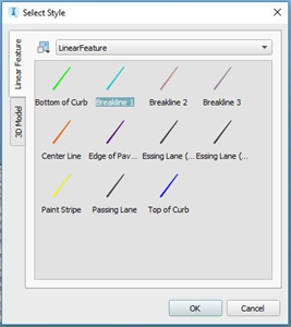
Select the correct line style for the feature you want to extract. For example, Bottom of Curb, Breakline, Center Line, etc.
Click "More Styles" to see all available linear feature styles. Important: When extracting features with the Manual method, you can change the line style at any time on the Extract Linear Feature panel of the Stack, if required. When using the Automatic method, you must pick the correct style at this point for the linear feature to be successfully extracted.
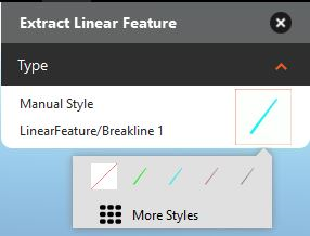
Click More Styles:
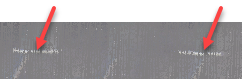
 Tip: For broken lines, select the Paint Stripe style. See the tips below for extracting broken paint lines from the point cloud.
Zoom in as necessary so you can clearly see the target lines for the road.
For Manual extraction: Click to select points along the line, and double-click to complete the feature.
For Automatic extraction: Click two points on the target linear feature. Click to specify the starting point, and double-click close to the starting point to set the draw direction and generate the linear feature. (See more tips below.)
Click and drag the points in canvas as needed to modify their position.
Access additional editing options on the right-click context menu.
With the linear feature selected, right-click, and click Show Cross Section View.
The Linear Feature Cross Section window displays. This view provides additional editing and viewing control as you modify the linear feature. See To edit linear features in a cross section view for more information.
Tips for using the Automatic method
Pick the correct line style for the linear feature you are modeling. For example, bottom of curb, breakline, center line, etc.
Zoom in to the area of the point cloud containing the road so you can easily see the points.
Use the ViewCube to select the Top view of the model to make it easier to precisely place points.
Make sure to click on points in the target line, not on empty spaces.
Place the two points at a reasonable distance apart depending on the feature being extracted. For most linear features (except broken paint lines), place the two points about 2-3 meters apart.
For broken paint lines, click a point in each of two consecutive solid paint segments to connect one blank interval.
Position the two points on a straight length of road, rather than a curve.
Adjust the view, if necessary, to avoid selecting points on the edge of the view.