To edit linear features in the cross section view
Open a cross section view to precisely edit linear features extracted from point cloud data.
With the linear feature selected, right-click, and click Show Cross Section View to open the Linear Feature Cross Section window.
This view provides additional editing and viewing control as you modify the linear feature. You can move the cross section gizmo in canvas or navigate directly in the cross section view, and changes are reflected in both views. Use the mouse wheel to zoom in or out in the cross section view.
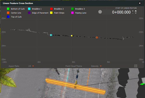
If you have an image CSV file associated with the point cloud data, consider using the Point Cloud Image Lookup tool to import the images and display another view of the features as you work in the Cross Section View. The image will update to show the location of the current linear feature station.
To navigate in the Cross Section View
The following image and descriptions highlight the controls you can use to make it easier to see and edit the vertices in the linear feature.
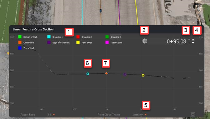
- A legend displays at the top of the window to identify the linear feature style for the vertices.
- Click
 to open the Cross Section Settings dialog to modify:
- Interval: The distance to move the cross section with the +/- buttons (labeled as 3 in the image). Note: If the linear feature has many curves, reduce the interval value as needed to ensure accurate extraction.
- Thickness: The depth of the cross section slice. Increase the thickness to see more of the point cloud along the linear feature.
- Auto vertex cleanup: With this option on, when you edit a virtual vertex in the cross section view to create a real vertex, and move to the next section, vertices between the two sections are automatically removed. This option is on by default.
- Use the +/- buttons to move a constant distance. The distance is set in the Cross Section Settings dialog.
- Use the arrow buttons to change the location of the cross section view. You can switch between critical stations or input different station values.
- Click the arrow to display options to change the point cloud theme, as desired to visualize the points. Available themes include: Intensity, Elevation & Intensity, Elevation, and RGB.
- Virtual vertex (hollow circle): A point that the linear feature goes through, but not a point that was extracted during the linear feature generation process.
- Real vertex (solid circle): A point that was selected or edited, or a point introduced by the algorithm during the linear feature generation process. Note: When you select a vertex in the cross section view, the feature style code and elevation display.
To add, modify, or delete vertices
- To modify the position of a virtual vertex and save it as a real vertex in a linear feature, click a hollow circle (virtual vertex), and drag the point. Or, click the circle and use the arrow keys on the keyboard to modify its position. Notice that the hollow circle is now solid to indicate that it is a real vertex. The real vertex stores the location information for the new position.
- Create linear features in the Cross Section View.
- Right-click in the cross section view, click Add Vertices, and select the linear feature line style from the menu.
- The vertex is placed at the cursor location.
- Click and drag to modify the position of the vertex, if necessary.
- Navigate in the view by using the + and - buttons or arrow buttons. As you move the cross section view, InfraWorks extracts the linear feature, and draws the line.
- To remove a vertex, select the point, right-click, and click Delete Vertices, or select the point and press Delete. The vertex is removed from the linear feature. Note that a base point (a real vertex extracted when generating the linear feature) cannot be deleted.
To group and ungroup vertices
Group vertices for easier modification in the cross section view. Moving a group of vertices together can be helpful when modifying points representing a solid structure, such as a curb or barrier. The groups are maintained in all relevant stations for the current session of InfraWorks. When you close and restart the application, the groups are not maintained.
| If you want to... | Then... |
|---|---|
| group vertices | Press and hold Ctrl while clicking vertices in the cross section view. Right-click and click Group Vertices. A solid frame displays around the group when one or more of the vertices is selected. |
| edit a vertex that is part of a group | Select a vertex to select the group, and select the vertex you want to change. A dashed frame displays around the group. Drag the vertex to change the location as required. The vertex is still part of the group, and the group frame adjusts as needed. |
| add vertices to a group | Select the group. While pressing Ctrl, click vertices to add to the group. Right-click, and click Group Vertices. |
| delete all vertices in the group | Select the group, right-click, and click Delete Vertices. |
| ungroup vertices | Select the group, right-click, and click Ungroup Vertices. |