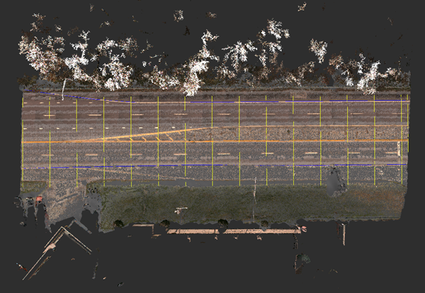
To generate transverse lines for linear features
For richer terrain information, generate lines perpendicular to the linear feature.
Linear feature extraction extracts key lines (breaklines or feature lines), but no additional surface information. Transverse lines, created at a constant interval, capture surface information for more precise roadway design.
- With the linear feature selected, right-click on the line (not a vertex), and click Generate Transverse Lines.
- In the Generate Transverse Lines dialog, specify the following:
- Line Length: Length of the transverse line. The length value is used if you do not select "Trim at outer breaklines."
- Distance between lines: Distance from one transverse line to the next.
- Distance between vertices: Distance between vertices used to capture site elevation data along the transverse line.
- Note: If you specify a value for the Distance between vertices that is greater than the Line Length value, InfraWorks uses half the Line Length value for the vertex interval, and generates transverse lines that meet the specified Line Length.
- Drape calculation: A calculation method used to calculate vertex elevation (z-coordinate) based on nearby point cloud points. Select Minimum elevation to drape to the "surface." Select Maximum elevation or Average elevation for noisy point cloud data to compensate for errors and create a consistent alignment.
- Trim at outer breaklines: Turn this option on to automatically trim the transverse lines to the outermost breaklines on either side of the linear feature.
- Click OK. Tip: To delete all of the transverse lines, open Model Explorer, expand Line, right-click Linear Features, and click View in Data Table. Select all items with the Manual Style Linear Feature/Transverse, and press Delete.