- In the scene view, select the polygonal mesh.
- From the Modeling menu set, select Mesh Tools > Insert Edge Loop >
 .
. The Insert Edge Loop Tool settings editor appears.
- Set the following options:
- Maintain position: Relative distance from edge
- Auto Complete: Off Note: When the Auto Complete option is off you can select a partial edge ring that is multidirectional without the edge loop being automatically inserted after you release your mouse button.
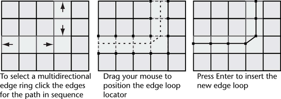
- Click an edge of the polygonal mesh to indicate the starting point of the partial edge ring where you want the new edge loop to be inserted on the mesh.
The edge is selected and a green vertex appears on the edge you clicked to indicate the selection.
- Click a second edge that you want to be the ending point of the partial edge ring. The second edge must be parallel to the first edge you selected.
All of the edges between the first and second edges you clicked become selected and a dotted green edge loop preview locator appears across the selected edge. The preview locator indicates where the new edge loop will be inserted across the mesh.
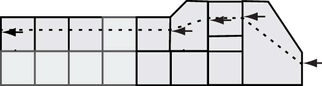
- To continue the existing edge ring path in a different direction, click on an edge that is directly adjacent to the edge you last selected to indicate the change in direction for the selection.
- Continue to select edges and/or change the direction in your edge ring path as described in steps 5 and 6 above.
 Note: You can change the direction of your edge ring selection path several times, but the path should not be constructed so that it crosses an existing area of selection. When the selection path intersects itself the edge insertion mode of the tool cannot determine where to insert an edge loop. In these situations, you need to perform multiple edge split operations.
 - If you want to cancel the selection of a particular edge at any time during the selection process, Ctrl + click on the desired edge. If you want to cancel the edge selection entirely, click anywhere in the scene view off of the mesh.
- When you have completed your selection process, either press Enter or right-click and select Complete Tool from the marking menu.
An edge loop is inserted at the location that was indicated by the preview locator on the polygonal mesh. The new edge loop remains selected so that you can perform additional operations on it.
- When you have completed your edge loop insertion, do one of the following to exit the tool:
- Choose the Select Tool in the Toolbox (Hotkey: q).
- Choose another tool or feature that performs the next operation on the selected edge ring.
For example, selecting the Move Tool to move the selected edge loop, selecting to extrude the selected edge loop, or converting the edge loop selection to faces.
Note: When the Auto Complete option is off, you can also insert a partial edge loop on faces that are not comprised exclusively of four-sided polygons by clicking two edges for any given face in sequence along the desired path. This specifies the direction of the selected ring path.