Using the Create Joint tool, you click-drag to interactively create a joint, specify its boundary axis for falloff, and define its initial area of influence, all in one operation.
As you create a joint and specify its region of influence (weighting), you determine how much of the surrounding vertices are affected when the associated model component is rotated or transformed about the joint using the Pose tool. You can later edit the region of influence and the position of the joint using the Weights or Move Pivot tools.
Expand any of the following sections for more detailed information on creating joints.
To create a single joint
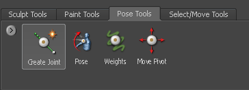
- In the Pose Tools tray, select the Create Joint tool.
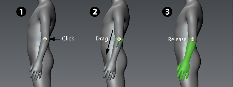
- Position the Create Joint tool cursor over the model so it displays as a dot, then click-drag on the model where you want the joint to appear. Two items appear when you drag:
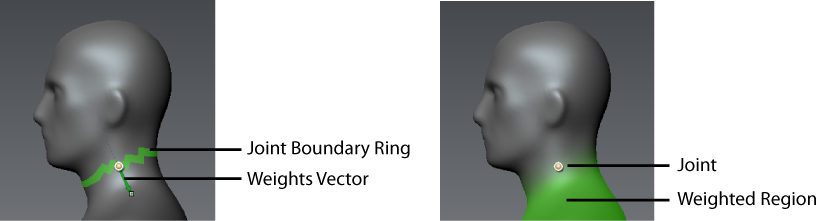
- Weights Vector: A green vector with an arrow head that you drag to define the initial width of the transition region on either side of the joint.
Drag the Weights Vector a short distance away from the joint (pivot) to define a small transition region, so that only vertices close to the joint are affected when you pose the model.
Drag a longer distance away from the joint to create a larger region of influence, so that more vertices further away from the joint are affected.
- Joint Boundary Ring: A jagged green ring of faces highlights at the joint location to indicate the boundary of the weighted region, balanced on either side of the joint.
Adjust the angle of this ring by dragging the Weights Vector around the joint. Depending on your requirements for deformation, you can adjust the joint boundary to appear perpendicular to the model component or at an angle. The angle of the joint boundary affects the default region of influence for the joint.
Both of these give you interactive feedback on the region of influence for this joint, and how deformations will occur in relation to the joint as you use the Pose tool.
- Weights Vector: A green vector with an arrow head that you drag to define the initial width of the transition region on either side of the joint.
- Release the mouse/stylus button after positioning the Weights Vector and the Joint Boundary Ring.
Two items appear:
- Joint: By default, the joint is centered within the ring of faces in the area you click.
When you place the joint, Mudbox attempts to center it in the volume by default. This makes it a quick and easy process for positioning the joint from any vantage point in the 3D View and provides an initially good default placement in most situations.
Note: You can change the default joint placement setting in the Create Joint properties. You can also reposition the pivot for the joint using the Move Pivot tool. See Adjust a joint's pivot location. - Weighted Region: The bright green color that diminishes with distance from the joint. This indicates the component of the model that moves, rotates or scales when you use the Pose tool.
The saturation of the weight color indicates the amount of influence the joint has on those faces when you pose the affected component. Fully saturated green indicates the faces are fully affected by the joint, less saturated color indicates less affect.
You can select from different methods for setting this initial weighted region using the Weights options in the Create Joint properties. You can also adjust the weighted region using the Weights tool. See Adjust a joint's region of influence.
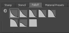
How the weight color diminishes with distance from the joint is initially based on the falloff curve selected in the Falloff tray when you select the Create Joint tool. You can further customize the falloff using the Weights tool. (See Adjust tool falloff.) The falloff curve is used as the guide along the range of influence you create when dragging the Weights Vector.
- Joint: By default, the joint is centered within the ring of faces in the area you click.
- To pose or deform the model component in relation to a joint, see Pose a model component.
To create multiple joints
- Select the Create Joint tool in the Pose Tools tray.
- In the Properties window, ensure the One Joint At A Time option is turned off.
- Click-drag on the mesh to place the first joint, dragging to indicate the area of the mesh you want the joint to influence.
The joint displays as a dot, and green highlighting indicates the region of influence for the joint.
Tip: Select from different methods for setting the initial weighted region using the Weights options in the Create Joint properties. - Click-drag on the mesh to create another joint.
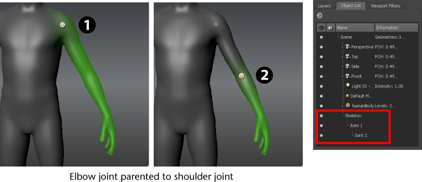
As you create additional joints, Mudbox automatically organizes the joint objects under a Skeleton object in the Object List. The hierarchical structure of this skeleton is determined by your placement of joints.
A smart auto-hierarchy logic creates joint hierarchies based on the influenced vertices as follows:
- If you create a new joint with an area of influence that is completely inside the area of influence for an existing joint, the new joint is parented to the existing joint.
- If you create a new joint with an area of influence that completely subsumes the area of influence of another joint, the new joint becomes the parent of the subsumed joint.
- If you create a new joint whose area of influence is completely outside the influence area of other joints, the new joint is added as a sibling.
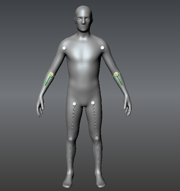
For example, if you create a shoulder joint with a weighted region on the whole arm, then create a joint at the elbow and drag to establish weighting toward the wrist, the elbow joint is auto-parented to the shoulder joint. A bone object displays between the two joints to indicate this relationship.
To create symmetrical pairs of joints
- Select the Create Joint tool in the Pose Tools tray.
- In the Properties window, do the following:
- Ensure the One Joint At A Time option is turned off.
- Set the Mirror option to the desired axis of symmetry you want joints copied across.
- Click-drag on the mesh to create a joint, dragging to indicate the area of the mesh you want the joint to influence.
One joint is created where you click, and another joint is created on the opposite side of your selected axis of symmetry.