Before you can create a nesting study for a model, you need to extract its appropriate CAD files (such as a series of .DXF files, or an .IAM, or .IPT file) into shapes that can be used for nesting.
Exclude Shapes from Extraction
 This feature supported as of the 2019.2.1 Update.
In some cases, before you extract an assembly, you might want to specify that parts of it be excluded from nesting; for example, if those parts have already been purchased or manufactured. You can set this up in two ways in Inventor. You must do this before extracting the files with Nesting Utility.
- In Inventor, set the BOM Structure property for the component to Purchased; or,
- In the Inventor Model browser, right-click the item and select
Exclude From Nesting.

Items marked as excluded will not be extracted for nesting in Nesting Utility. Sub-assemblies or parts inherit the exclude property of their major assembly.
No Items Marked as Excluded "middle.iam" Marked as Excluded "top.iam" Marked as Excluded All parts of the assembly will be nested middle.iam and the part it contains, bottom.ipt, will be excluded from the nest. All items in the assembly will be excluded from the nest. 


Extract Shapes for Nesting
- Click
Sources
 on the
Inventor Nesting ribbon.
on the
Inventor Nesting ribbon.
The Sources dialog box opens.
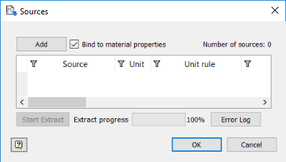
- Select
Bind To Materal Properties if you would like shapes to automatically update whenever material properties are changed while you work on this nest.
Autodesk recommends leaving this selected.
- Depending on whether or not you have Vault installed, click the appropriate button or option.
- If you do not have Vault installed, Click Add.
- If you have Vault installed, the Add button is replaced by a drop-down box. Select the appropriate drop-down option: Source Files or Vault Source Files.
- Select and add any files that you want to extract.
These can be part (IPT), assembly (IAM), or individual DXF files. You can add multiple files at once. All files, included referenced files, are listed in the Sources dialog box.

- Check that the unit setting is correct for all files.
It is possible for a DXF file not to have had a unit value defined for it in the source application. In this case, Inventor Nesting assigns it the default unit setting of the current document. To change this setting, select a value from the drop-down box in the Unit Rule column. (This is not editable for IPT or IAM files.)
- From Source Document: Value from the source application (for example, AutoCAD).
- From Current Document: Value used in the current Inventor document.
- Custom: Manually select from the drop-down box in the Unit column.
- Optional: If you have added DXF files, show the Material Name column and select an appropriate material ID for each DXF file.
You can also do this later in the Source Nesting Properties dialog box.
- Optional: Show the Configuration column and select an appropriate configuration file for your shape file.
A configuration file is a customizable set of instructions on how to extract files. For example, it can define that the fifth layer of a DXF file contains geometry that should be excluded from the nest. Normally you should not have to switch configuration files. You can set a default configuration file in the Extract tab of the Options dialog box.
Tip: Right-click a row to edit the corresponding configuration file. See Extract Configuration Editor Dialog Box Reference. - Click
Start Extract in the Sources dialog box.
The shapes are extracted and listed in the Inventor Nesting browser and shown in the application window. They also remain listed in the Sources dialog box whenever you reopen it.

Should you make changes to any of the referenced CAD files, you will need to reopen the Sources dialog box and extract them again. Files that need to be extracted again are indicated by an icon
 in the
Inventor Nesting browser.
in the
Inventor Nesting browser.