Use the Options dialog box to set global values for TruPlan across all documents.
- Click Options on the TruPlan ribbon.
Laser Projection Output
Use this tab to set default values for the Laser projection data output.
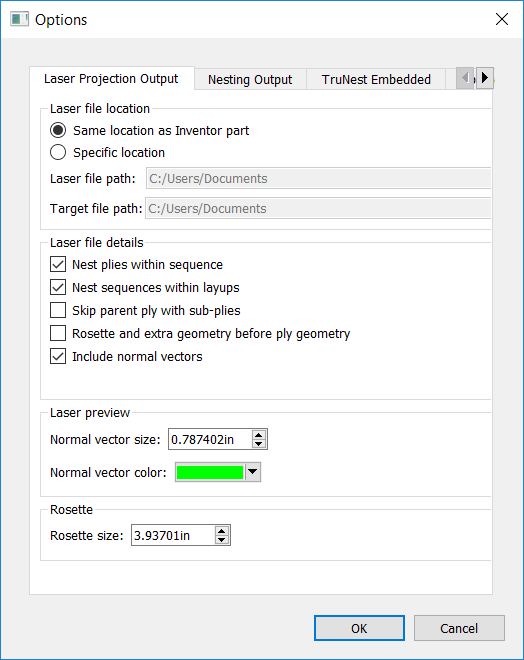
- Laser File Location
- Set the default file locations for TruLaser output; for example, a hard disk on a computer that is connected to a laser projector. In the case of LPT files, you must set the laser and target (tool data) paths separately.
- Laser File Details
-
- Nest Plies Within Sequence: Migrate the hierarchy of plies within sequences in the TruPlan browser to the laser output file. In other words, during projection, all plies within a single sequence will be projected at the same time
- Nest Sequences Within Layups: Migrate the hierarchy of sequences within layups in the TruPlan browser to the laser output file. This option is only supported by Virtek, LPT, Assembly Guidance, and SL Lasers. In other words, during projection, all sequences within a single layup will be projected at the same time.
- Skip Parent Ply With Sub-Plies: Sub-plies are contained within the parent ply; use this option to exclude the parent ply and only include the sub-plies in the output. You might do this if you are only laying the sub-plies and do not need to see a projection of the entire ply. Conversely, you might want to actually include the parent before projecting the sub-plies so that the operator can see what the entire ply is supposed to look like.
- Rosette And Extra Geometry Before Ply Geometry: Information is written to the laser output data file in sequence. Select this to write rosette and extra geometry information to the file before ply geometry.
- Include Normal Vectors: Select whether to include normal vectors when creating 3D laser output. Normal vectors are calculated based on the reference surface and are crucial to getting correct laser projection. Autodesk recommends leaving this selected.
- Laser Preview
- Adjust preview settings for the Laser Projection Data dialog box.
- Normal Vector Size: If vectors are enabled, set a value appropriate for your model; larger models need a larger vector size.
- Normal Vector Color: The color of the normal vector; most projectors use green for projections.
- Rosette Size
- Set a value appropriate for your model; for example, a rosette size of 10mm will be too difficult to see compared to a large object like a wing.
Nesting Output
Use this tab to set default values for the nesting data output.
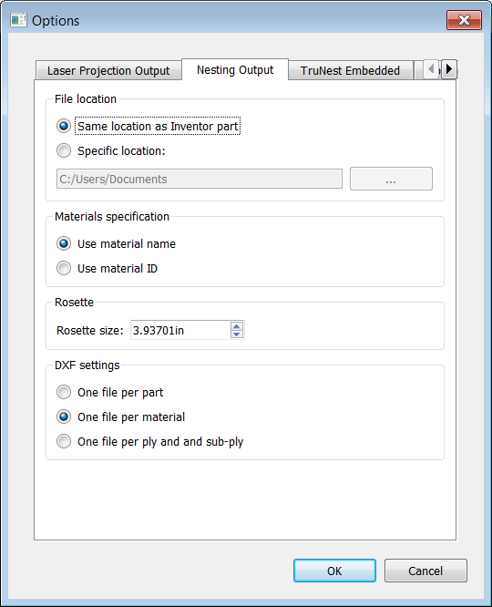
- TruNest File Location
- Set the default file location for TruNest output; for example, the location where a TruNest system is expecting input part data.
- Materials Specification
- Select whether to use the material ID or name entered in the Properties tab of the Material Library dialog box. In some cases, material IDs are very long and include special characters, which can cause problems with some nesting software and should be avoided in favor of material names. In other cases, you might be using a material ID very specific to your organization, and you can choose whether to include this ID, or a more generic material name, in output.
- Rosette Size
- Like with laser projection, set a value appropriate for your model; use larger rosettes for large parts.
- DXF Setttings
- Select whether to create one DXF file for the part, or separate DXF files based on materials or plies.
Update
Use this tab to enable or disable automatic updates to the display while you work on your project.