Working With Laser Projectors
Set up projectors to be included with laser projection output. This can include creating 3D text effects and additional geometry. Start by setting up laser targets, then create your projectors and other features.
Set Up Laser Targets
Before creating a laser projector, you need to set up targets. Most laser projection systems need a minimum of six targets for proper alignment. When you choose a point that will be used as a target, think about what the position of the laser projector will be in relation to the part when working with laser projection software such as TruLaser. Targets should be clearly visible to the laser projection system, and easily located to ensure that the laser will be reflected so that an accurate frame of reference can be established.
-
Create a point to be used as a target.
You do not have to project a point if it is going to be used as a laser target.
-
Click Laser Target on the TruPlan ribbon.
- In the Laser Target Point dialog box, enter a name and comment (optional) for the target.
- Click the selection arrow
 and select the point you want to use as the target.
 -
If you want this point to also be used as drift check for the laser, select Drift Check Point.
When you set up a laser that support drift check points, it uses the points to orient itself, then re-scans them intermittently to make sure nothing has moved. Autodesk recommends having two or more drift check points.
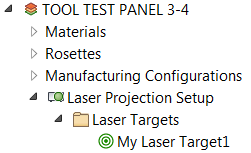
The target is created in a Laser Targets folder under the Laser Projection Setup node in the TruPlan browser.
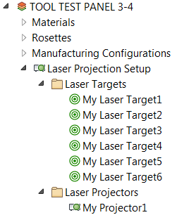
Repeat this procedure for any additional targets you want to create. Remember that you should have six or more targets for a properly aligned projection system.
Create a Projector
Once you have created laser targets, create a projector that will use them.
- Click Laser Projector on the TruPlan ribbon.
- In the Laser Projector dialog box, enter a name and comment (optional) for the projector.
-
Click the selection arrow
and select the targets you want to use with the projector.You can select multiple targets. There should be at least six, and they should be clearly visible to the projector.
The projector is created in a Laser Projectors folder under the Laser Projection Setup node in the TruPlan browser.
Create Extra Laser Geometry
Create extra geometry to complement your composite data. Some examples of this could be a crosshair used to verify that a tool is in the right spot, a center line to indicate the mid-point of a part, or an outline that shows an operator where to stand. In other words, these are elements you would not necessarily add as regular surface geometries. This geometry can be valid for a single ply or a group of plies. You cannot use reference planes or infinite line segments as extra geometry.
-
Select an element in the TruPlan browser under which to add geometry.
This can be a ply, sequence, or layup. In the case of a sequence or layup, the geometry can be created for all plies and cut pieces within that item.
-
Click Extra Geometry on the TruPlan ribbon.
The Extra Laser Geometry dialog box opens.
-
In the Apply To box, select which plies the geometry should apply to, based on the element you selected in the first step.
- All Plies: All plies in the model.
- Plies Below: All plies following the current selection in the TruPlan browser within the parent node.
- Until Next: All plies following the current selection until the next occurrence of extra geometry applied in this way within the parent node.
- Parent Only: All plies in the parent node of the current selection.
- Select the kind of geometry to create.
- 2D Composites Laser Projection: For 2D laser projection.
- 3D Composites Laser Projection: For 3D laser projection; (Core sampling offsets are applied for each piece of open geometry.)
- Composites Nesting Geometry: To be used in conjunction with used in conjunction with Autodesk TruNest.
- Optional: Right-click the new geometry node and select Rename to give it a new name.
-
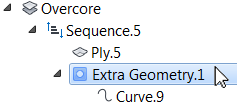
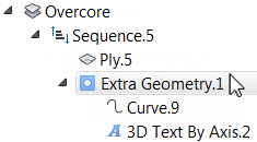
Click the new geometry node and add geometry to it (for example, a curve).
If you plan to add 3D text to the geometry, the geometry should provide an identifiable anchor point and direction for the text. You will specify these in the 3D Text dialog box.
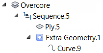
The geometry is created and applied to the plies you selected.
Create 3D Text
You can display text with your laser projector on one or more plies in the laser file. You can use custom text or text variables. You must have created extra geometry first so you can add 3D text to it.
-
Select an Extra Geometry node in the TruPlan browser and click 3D Text on the TruPlan ribbon.
The 3D Text dialog box opens.
-
Enter a name for the 3D Text component in the Name box.
-
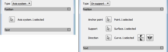
From the Type box, select how the text will be placed.
- Axis System: Text is placed at the origin of a rosette in the direction of the X-axis, with the text height in the Y direction. Z-direction determines whether the text is facing in or out.
- On Support: Text is placed at an anchor point, using a surface as support, along a defined direction.
The option you select determines the controls that are shown under Position in the dialog box.
-
If you selected Axis System in the previous step, click the selection arrow
under Position and select an axis system in the TruPlan browser.If you selected On Support in the previous step, use the selection arrows
under Position to add the following elements from the TruPlan browser:- Anchor Point: A point that defines the origin of the text.
- Support: A plane or surface that defines the orientation of the text.
- Direction: A line or curve that defines the direction and angle of the text; use the flip and mirror buttons

 to change the direction or orientation of the text if needed.
-
Under Text, enter the text you want to use and set its size.
When the text is passed to the projector, the projector will determine the most efficient way to project it with minimal flicker. The more text there is, the greater the chance that flicker will occur.
-
Under Available Parameters, select a text variable and click Add Text
 to include it in the text that will be generated.
The variables represent names of elements in your project. For example, %LAYUP% is the layup of the ply, %ORI% is the orientation of the text, %SOURCE% is the path of the file, and so on.
-
Click Validate to make sure that there are no problems with your text, such as unsupported characters or invalid variables.
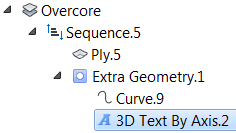
The 3D text is added beneath the extra geometry node in the TruPlan browser. Its name includes a suffix indicating its type; that is, "By Axis" or "On Support."
To rename the 3D text node, right-click it and select Rename.
Add Laser Parameters
Add non-geometric parameters, such as queries to run or messages to display when proceeding through a projection. These are specific to TruPlan and laser projection (they do not support Inventor parameters, for example).
-
Select an Extra Geometry node in the TruPlan browser and click Laser Parameter on the TruPlan ribbon.
The Laser Parameter dialog box opens.
-
Select a type of parameter to add.
- Information: Text to display on the projector panel; for example, "Don't forget to check the grain." Some projectors use this parameter for this, others use the Note parameter.
- Message: Text to display on a device connected to your projector; for example, an LED message display.
-
Graphic: Enables you to display a digital photo during projection. This is often used for showing what the final result should be for a ply. For example, you could enter ply1.jpg. to show a picture of what Ply1 is supposed to look like when done correctly. By default, the projector will look for image files in the same folder as the laser projector file, or you can enter the full name and path, such as C:\images\ply1.jpg. If an image file name is not found, it is skipped.
Tip: You can use variables to show the appropriate image for the current ply, provided the ply and its related file have the same name. For example, enter C:\images\%PLY%.jpg to display ply1.jpg for Ply1, ply2.jpg for Ply2, and so on. -
Query: A 'yes' or 'no' question during projection that needs to be answered by the operator before projection continues; for example, "Did you check the grain?" The answer is recorded in an output report. Queries are only supported by certain brands.
-
Literal: Text to include in the file exactly as written. This can be useful for supporting features of your projector that might not be included in this list of parameters.
Note: Use this feature judiciously. Bad text can invalidate your output file. -
Note: Text to display on the projector panel; for example, "Don't forget to check the grain." Some projectors use this parameter for this, others use the Information parameter.
- Add variables as you would when creating 3D text.
You should also review the Laser Projection Output tab of the TruPlan Options dialog box for further details on controlling laser output.