Working with Sub-Plies
You can divide a ply into sub-plies. To do this, you must first project at least one curve onto the surface of the ply to use as a divisor ("splice curve"). For best results, you should project curves that were created using the Inventor "Curve on Face" feature.
You should create simple projections for this purpose, and they must not be closed or self-intersect.
|
|
|
Curve projections should ideally surpass the boundary edges of the ply; if they do not, TruPlan can extrapolate so that they do.
Create a Subdivision and Sub-Plies
-
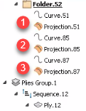
Create splice curves for your sub-plies and project them onto the surface of a ply.
-
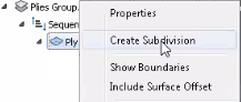
In the TruPlan browser, right-click the ply under which you want to create the sub-plies.
-
Select Create Subdivision to open the Subdivision dialog box.
-
In the TruPlan browser, select one or more valid projections with which to divide the ply into sub-plies.
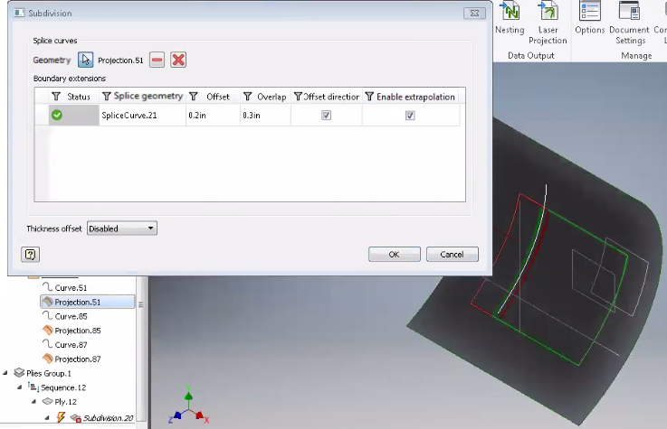
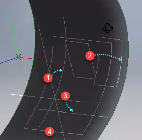
The projections you select are listed in the Subdivision dialog box. Icons in the Subdivision dialog box indicate whether the projections are valid (
 ) or invalid (
 ) for creating sub-plies. Each sub-ply is highlighted in its own respective color in the TruPlan window.
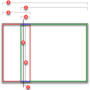
1. Whole ply
2. Sub-ply
3. Sub-ply
4. Overlap of sub-plies
5. Splice curve projection (determines the division line between plies)
6. Mid-point of the overlap (Offset is the distance between this and the splice curve projection)
7. Offset direction
- Adjust offset and overlap in the Subdivision dialog box.
-
If a curve projection does not surpass its boundary limit, select Enable Extrapolation in the Subdivision dialog box.
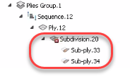
When you finish creating the sub-plies, they are listed in the TruPlan browser along with their subdivision.
-
To make sure to use this subdivision in your part file, right-click it in the TruPlan browser and select Include to make it part of the active maunfacturing configuration.
Edit Subdivisions
- In the TruPlan browser, double-click a subdivison to open the Subdivision dialog box.
- In the Subdivision dialog box, add splice curves and adjust offset and overlap as you would when creating a subdivision.
Edit Sub-Plies
You can edit sub-ply properties such as boundary, color, and clearance. If you created the sub-plies in TruPlan, you must convert them to manual first if you want to be able to edit their boundaries.
-
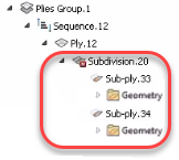
If you created the sub-plies in TruPlan, right-click their subdivision and select Convert To Manual.
The geometry information (folders) for the sub-plies is moved to the Geometry section of the TruPlan browser. You can now edit all properties of the sub-plies, including the geometry used to create them.
-
In the TruPlan browser, double-click the sub-ply you want to edit.
The Sub-Ply dialog box opens. It contains a subset of the properties you would edit for a standard ply.
-
Make your changes as you would when editing a ply:
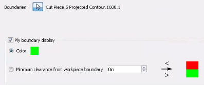
- Boundaries (not editable for sub-plies you created unless you converted the sub-plies to "manual.")
- Ply Boundary Display (visibility, color, workpiece clearance)