View a model in the 3D viewer
The Upchain 3D viewer enables non-CAD users to preview CAD model files directly within Upchain. The 3D viewer includes tools to analyze the design, create and save markups, and initiate Inventigation requests.
Open a CAD model in the 3D viewer
There are three ways to open a CAD model into the 3D viewer:
In the BOM (
 ) table in the center view, double-click the Item has model attached icon
  corresponding to the item you want to open in the 3D Viewer.
If visualization has not yet been generated (
 ) or is in the process of being generated (
 ) and you attempt to open the 3D Viewer, Upchain displays an error message indicating visualization is not yet available.
Learn about regenerating the item visualization.
Click the item image at the top of the item details pane.
Click the item actions icon
 to the left of the item name. Select View > Model.
3D viewer interface overview
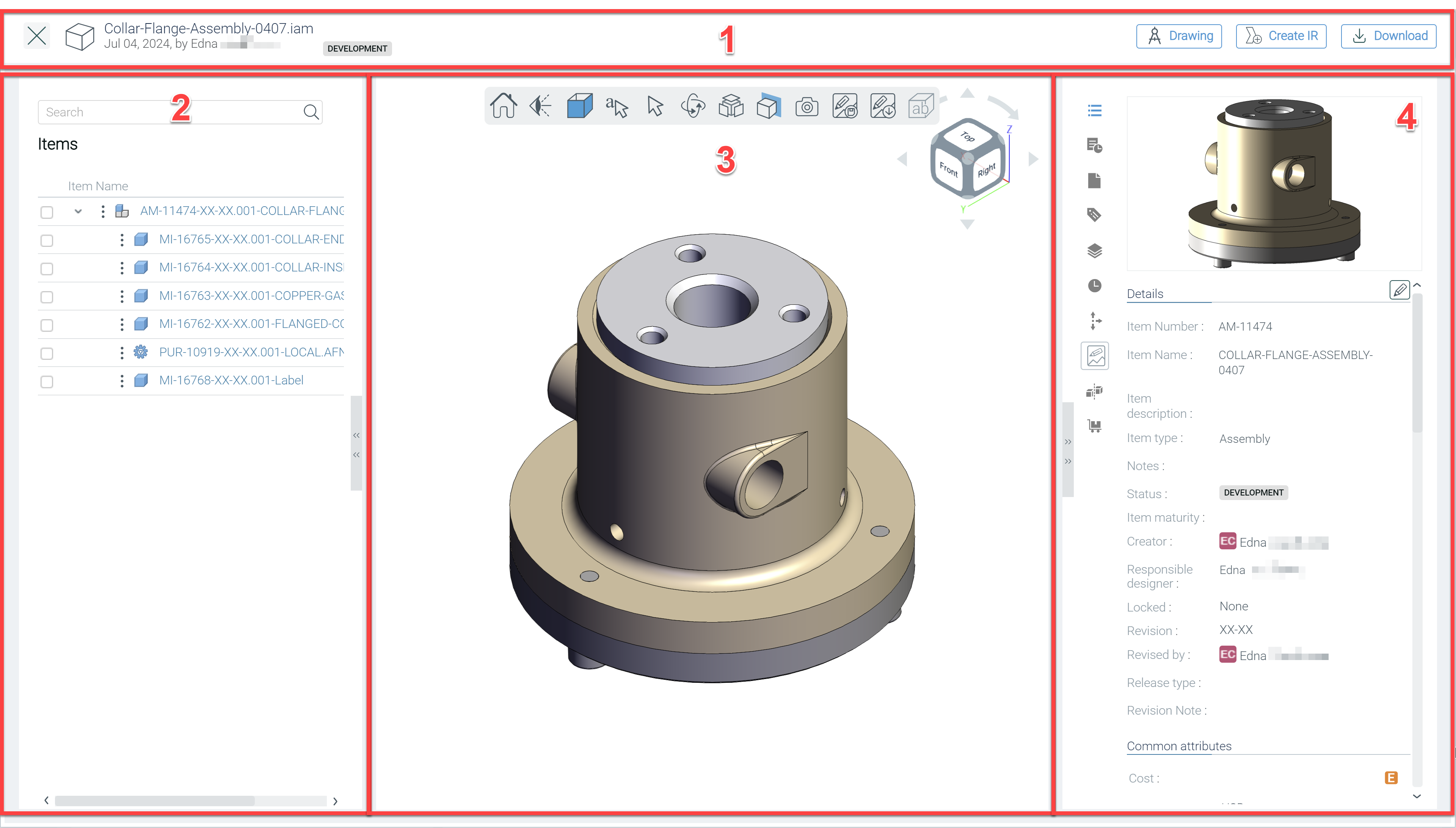
The 3D viewer interface is divided into:
Header - View information about the opened item. You can also download CAD files for the opened model, download a PDF translation of its associated drawing, or create an Investigation request (IR) from here.
Left pane - View the item's bill of materials. Click an item to open its details in the right detail view and to highlight it in the main pane.
Main pane - View the 3D model, DIE, or weldment, and perform additional actions on it.
Right pane - View more details about the opened item including its attributes, attached documents, associated activities, CAD attributes, CAD file history, saved markups, and item compares.
Note: This pane only shows details of the parent item loaded into the 3D viewer.
The main pane overview
The main pane is where you manipulate the model in a way that enables you to analyze the design thoroughly.
- Left-click and hold to rotate the model around its origin.
- Right-click and hold to move the model without changing its orientation.
- Scroll up and down to zoom in and out.
- Use the View cube
 to select specific orientations and rotate the model.
 ) to return the model view to its default orientation. This icon does not reset the display style, exploded view, or cutting planes but does remove any redline shapes.
The camera menu
The camera menu allows you to switch between a variety of different view orientations for the currently-selected CAD file.
Hover your cursor over the Camera menu icon ( ) to select one the following view orientations.
| Icon | View |
|---|---|
 |
Face View |
 |
Isometric View |
 |
Orthographic View |
 |
Perspective View |
 |
Left View |
 |
Right View |
 |
Bottom View |
 |
Front View |
 |
Back View |
 |
Top View |
The model draw menu
The model draw menu allows you to switch between a variety of different display styles for the currently-selected CAD file.
Hover your cursor over the Model draw icon ( ) to select one the following display styles.
| Icon | Name |
|---|---|
 |
Shaded with Line View |
 |
Shaded View |
 |
Hidden Line View |
 |
Wire Frame View |
The redline menu
The redline menu is used for adding markups to the item. Read on to learn more about how to manage markups.
Hover your cursor over the Redline icon ( ) to select one the following options.
| Icon | Name |
|---|---|
 |
Redline Circle |
 |
Redline Rectangle |
|
Redline Note |
 |
Redline Freehand |
Add redline shapes and notes
- Hover your cursor over the redline menu icon (
 ), then select the desired option from the menu.
- To add circles, rectangles, and freehand markups, click and drag over the area of the model you want to add the shape to.
- To add notes, click the area you want to add markup to, then type your comment in the text box that appears.
Move redline shapes and notes
To move a redline element to another part of the model, click and drag the object.
Remove redline shapes and notes
To remove added shapes or notes you can:
- Click the Home icon () to remove all shapes
- Highlight individual shapes and press the Delete key.
The select menu
The select menu enables you to measure the distances of components in the viewer. There are several options to measure a component, listed below, and shown in the screenshot of the icons from left to right.
Hover your cursor over the Select menu icon ( ) to select one of the following measuring tools.
| Icon | Name | Description | Method |
|---|---|---|---|
 |
Measure Angle | Measures the angle between two faces. | Select the tool, then select the desired faces. |
 |
Measure Distance | Measures the distance between two faces. | Select the tool, then select the desired faces. |
 |
Measure Edge | Measures the length of a selected edge. | Select the tool, then select an edge in the model. |
 |
Measure Point to Point | Measures the length between two points. | Select the tool, then select two points in the model. |
 |
Normal Select | Reverts the cursor back to the normal select tool. | Select the option. |
The camera type menu
The camera type menu allows you to switch between a variety of different camera types for the currently-selected CAD file.
Hover your cursor over the Camera type icon ( ) to select one the following camera types.
| Icon | Name | Description |
|---|---|---|
 |
Walk View | View the model on a horizontal plane as if walking around it. |
 |
Turntable View | View the model by revolving it on a fixed horizontal plane. |
 |
Orbit View | View the model by revolving horizontally or vertically, with a fixed center point. |
The explode option
The explode option allows you to virtually pull the components apart in the viewer to examine each part individually.
- Hover your cursor over the Explode icon (
 )
)- The explode slider appears.
- Move the slider to the right to separate the parts.
- Move the slider to the left to bring the parts back together.
The cutting plane menu
The cutting plane menu allows you to virtually slice through the currently-selected model to see the inside components.
 ) to revert the model to its original view.
- Place your cursor over the Cutting plane icon (
 ).
). - Select one of the following axes:
| Icon | Name |
|---|---|
 |
X Cutting Plane |
 |
Y Cutting Plane |
 |
Z Cutting Plane |
 |
Invert X Plane |
 |
Invert Y Plane |
 |
Invert Z Plane |
Update the CAD model's thumbnail displayed in the eBOM table
When viewing a CAD model in the 3D Viewer you can use a new view of the model to be the thumbnail displayed in the BOM table.
- In the 3D viewer, position the model at the required orientation. Apply any desired display styles.
- Click the Thumbnail update icon
 .
. - Refresh the BOM page, to see the updated thumbnail in the BOM table and item details pane.
Markups
A markup enables you to save your redline shapes and notes to a design to intiate further discussion on possible design changes or errors. Typically, you would initiate an Investigation request and associate a markup to it to begin the review process.
Save a markup
- Add redline shapes and notes as desired.
- Click the Save markup icon (
 ).
). - Input a name for the markup.
- Click Done.
The markup is saved to the Markups tab ( ) in the right pane. Double-click on a markup to load it into the main pane.
Download a markup
- Load the desired markup into the main pane.
- Click the Download markup icon (
 ) to download your markup as a
 .pngfile.
Initiate an Investigation request
- Load the desired markup into the main pane.
- Click Create IR in the Header.
- Fill out all information as required, then click Create and start.
The IR is created and its workflow is started. You can locate the IR in the Business processes tab of the item or the Business processes section of the project. The image used for the IR is a screenshot of the current state of the model in the 3D viewer. The markup associated with the IR is found in the Markups tab () of the IR.
Remove all PMIs
This option removes product and manufacturing information (PMIs) if they exist in the CAD model. This icon is disabled if the model does not have PMI.
- Click the PMIs icon (
 ) to show/hide PMI information.