Specular BRDF (Bidirectional Reflectance Distribution Function)
This tutorial explores various Specular settings found within the Standard Surface shader.
BRDF
A bidirectional reflectance distribution function (BRDF) describes the reflectance properties of a surface by specifying the amount of radiance incident from one direction that is reflected into another direction, with respect to the surface normal.
The main characteristics of a physically plausible BRDF are the symmetry between the incident and reflected directions (Helmholtz reciprocity) and that the total reflected power for a given direction of incident radiation is less than or equal to the energy of the incident light (Energy conservation).
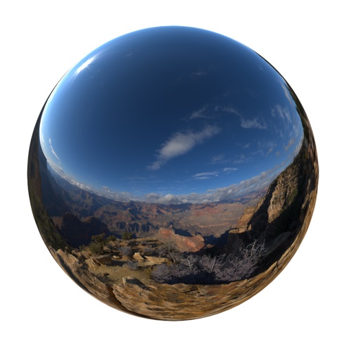
A Specular BRDF model is view-dependent and can take into account anisotropy and Fresnel effects at grazing angles. Arnold uses a Cook-Torrance BRDF.
The light ray that hits a surface is called the Incident Ray, and the angle at which it hits is called the Angle of Incidence (as shown in the figure below). Light energy reflected must be less than or equal to the light incoming to a surface (we cannot "add" light). On the surface, the ray is either reflected or refracted, and it can eventually be absorbed by either medium.
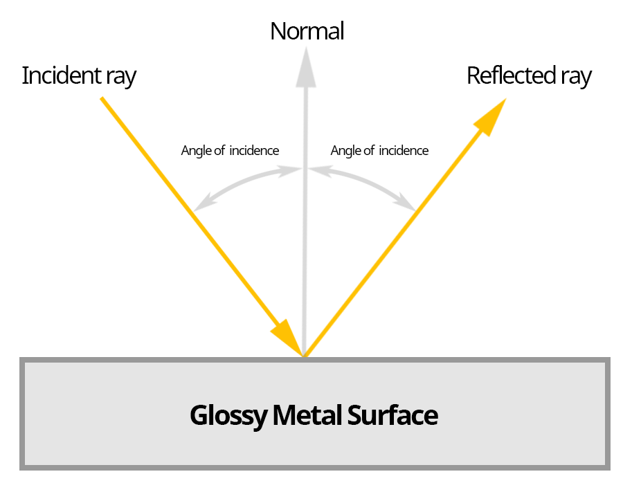 |
Angle of incidence, incident, and reflected rays
Reflectance at Normal
Note: The Fresnel effect is named after the French physicist Augustin-Jean Fresnel, who first described it. This effect states that the strength of reflections on a surface is dependent on the viewing angle. The amount of reflection increases on surfaces viewed at a glancing angle.
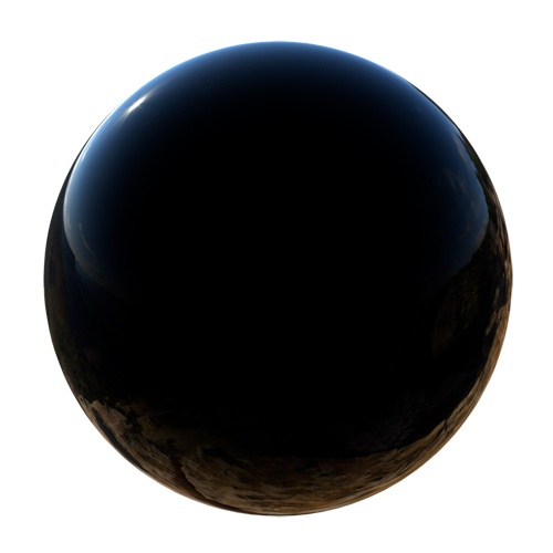
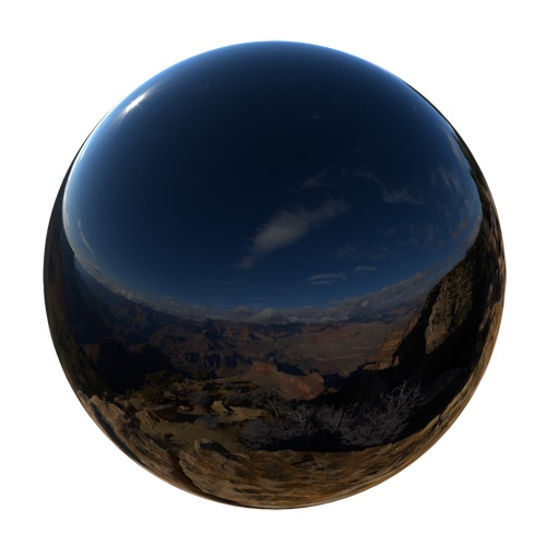
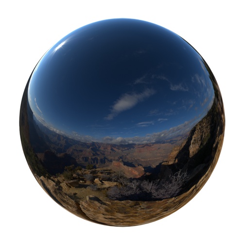
When IOR is greater than 1 in the Standard Surface shader, the reflectance of the object will be view-dependent and vary according to Fresnel equations. The Standard Surface shader uses Schlick's approximation of the Fresnel equations and can be controlled by using the IOR of the material. At low values, the material behaves as a perfect dielectric, like plastic. With higher values, the material becomes a near-perfect conductor or metallic surface.
 |
 |
 |
 |
Fresnel is present in all materials in some form, being the most common examples glass and water. The example below shows the effect of Fresnel on a wooden table. Notice how the reflection on the table appears more reflective as the camera's viewing angle becomes shallower.
Variation of a Specular BRDF with respect to the view direction.
In the example below, the cube has a Standard Surface shader assigned using IOR. The Fresnel effect is visible. The specular glossy reflection appears brighter when the camera's viewing angle becomes shallower.
Micro-Facet Surfaces
Cook-Torrance is a micro-facet BRDF based on Micro-facet Models (See for instance "Microfacet Models for Refraction through Rough Surfaces" by Walter, Marschner, Li and Torrance, Eurographics 2007).
These models consider that surfaces that are not perfectly smooth and are composed of many very tiny facets, each of which is a perfect specular reflector.
These microfacets have normals that are distributed about the normal of the approximating smooth surface. The degree to which microfacet normals differ from the smooth surface normal is determined by the roughness of the surface.
The animations below show how surface roughness can affect specular reflections.
 |
 |
In the examples below, you can see that the specular reflection appears stretched when the surface becomes 'bumpy' or 'rougher'.
 |
 |
Anisotropy and Roughness
An example of an anisotropic material would be asphalt concrete. This effect is evident on the surface of a wet road. Notice that the wet surface appears diffusely darker and specularly brighter. When you are far from the surface, the stretched anisotropic reflection is more obvious on the ground. However, when you get closer, the stretched reflection becomes smaller due to the change in viewing angle. The anisotropic highlight size depends on the viewing angle.
 |
 |
Dry, diffuse road surface vs. wet anisotropic road surface
The example animations below show the effect of specular roughness when using anisotropy (0, 0.5, 1). The roughness values have been animated from 0 to 1 to demonstrate the effect.
 |
 |
 |
Anisotropy values left to right: 0, 0.5, 1.
Anisotropy Example
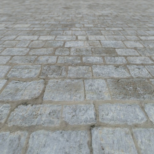
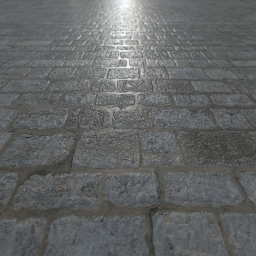
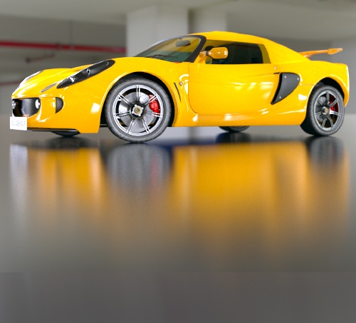
The images below show the difference between rendering with and without anisotropy on a floor surface. Both shaders have Roughness set to 0.2.
 |
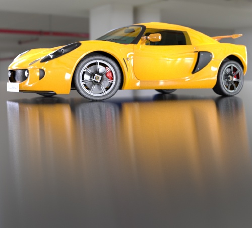 |
| Floor shader Anisotropy: 0 | Floor shader Anisotropy: 0.8 |