
Use the AutoCAD Electrical toolset Linking tools to associate non blocked text to previously placed template blocks.
Through the modification of a template block, you have control over which attributes are inserted and visible. All necessary attribute definitions are placed using the properties of the existing text entities, such as justification, height, and location. If multiple template block files are selected, the value of the text is added to the previously defined template block attributes as hidden attributes and the text is not removed.
Linking Results:
- The selected text entities are replaced with an AutoCAD Electrical toolset attribute.
- Colors change to distinguish what has been already converted as defined in the WD_M block.
- Temporary lines display the link.
The Link Descriptions tool links simple text as Description 1-3 attributes on an AutoCAD Electrical toolset block file. You can link them as description attributes to one or more existing template block definitions. During the conversion process, the text entity is removed and replaced with the next available description attribute, up to 3.
Link descriptions
- Click
 . Find
- Respond to the prompts as follows:
Select objects: Select 9PB, right-click
Select text to fill in next available DESC attribute:
Select LIGHT A, right-click
Select objects: Select 10PB, right-click
Select text to fill in next available DESC attribute:
Select LIGHT B, right-click
Select objects: Select 11PB, right-click
Select text to fill in next available DESC attribute:
Select LIGHT C, right-click
Select objects: Select 12PB, right-click
Select text to fill in next available DESC attribute:
Select LIGHT D, right-click
Note: You may have to right-click several times to exit the command.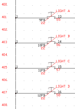
Colors change to distinguish what has been converted and temporary lines display the link.
- Click
. Find
- In the Schematic Report dialog box, specify:
Report Name: Component
Active Drawing
Click OK.
- If asked to QSave the drawing, click Yes.
In the Report Generator dialog box, notice that 9PB-12PB are still listed in the TAGNAME column of the report.
- In the Report Generator dialog box, click Change Report Format.
- In the Component Data Fields to Report dialog box, select Desc1 from the Available Fields list.
Desc1 moves into the Fields to report list. These are the fields to display in the Component report.
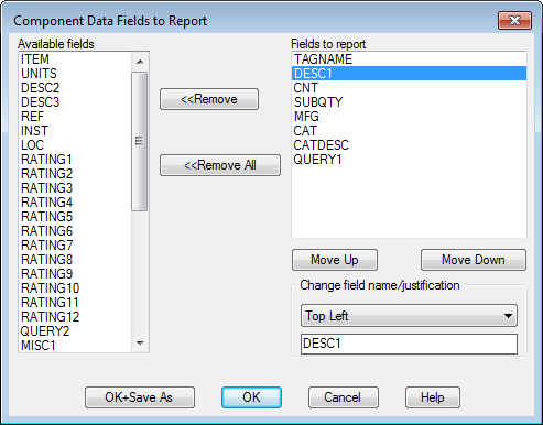
- Click OK.
The Report Generator dialog box now lists the TAGNAME and DESC1 values from the active drawing.
- In the Report Generator dialog box, click Close.