Use the Multiple Insert Component tool to insert a string of normally open limit switches into wires that are tied to the PLC module.
Insert a limit switch
- Click
 . Find
- In the Insert Component: JIC Schematic Symbols dialog box, click Limit Switches.

- In the JIC: Limit Switches dialog box, select Limit Switch, NO.

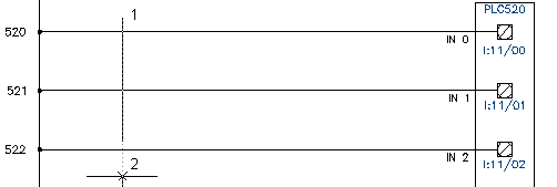
- Respond to the prompts as follows:
Component Fence, From Point:
Select above the wire at line reference 520 (1)
Component Fence, From Point: to:
Drag below the wire at line reference 522, click the point (2), right-click
- In the Keep dialog box, select:
Keep this one
Show edit dialog box after each
Click OK
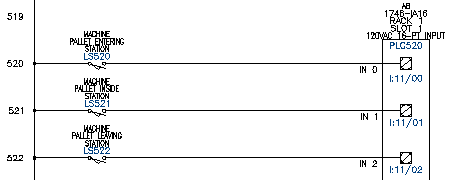
- In the Insert/Edit Component dialog box, specify:
Component Tag: LS520
Description: Line 1: PALLET ENTERING
Description: Line 2: STATION
Location code: MACHINE
Click OK.
Note: In the Insert/Edit Component dialog box, Component Tag section, you can use the Use PLC Address button to add the I/O Address as the component tag. - In the Keep dialog box, select:
Keep this one
Show edit dialog box after each
Click OK
- In the Insert/Edit Component dialog box, specify:
Component Tag: LS521
Description: Line 1: PALLET INSIDE
Description: Line 2: STATION
Location code: MACHINE
Click OK.
- In the Keep dialog box, select:
Keep this one
Show edit dialog box after each
Click OK
- In the Insert/Edit Component dialog box, specify:
Component Tag: LS522
Description: Line 1: PALLET LEAVING
Description: Line 2: STATION
Location code: MACHINE
Click OK.
The normally open limit switches are inserted into the drawing.