
Edit the Circuit Builder spreadsheet to add the instructions for building the circuit.
- Open ace_circuit_builder.xls for edit using a spreadsheet software. See Circuit Builder spreadsheet overview for the location of this file.
- Copy the 3ph_H sheet and rename it 3ph_H_custom as referenced in the ACE_CIRCS sheet.
The changes in the circuit codes sheet must correspond to the changes made to the marker blocks in the circuit template drawing. You can delete the lines in the sheet that match the code values from the marker blocks you deleted, XF01 and KVAR1. If you decide not to delete them from this sheet, it is not a problem. These lines are ignored and not displayed on the Circuit Configuration dialog box if the corresponding marker blocks are not found.
- Locate the CODE value XF01.
- Delete all the spreadsheet rows to the point where the next non-blank CODE value begins, such as XF02.
- Repeat for CODE value KVAR1.
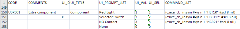
Add a section for the new marker block you added with a CODE value of USR001. Add this new section at the bottom of the sheet after the last non-blank row.
- Enter USR001 in the CODE field in the blank row.
- Enter Extra Component in the COMMENT field.
It is displayed in the left-hand Circuit Elements section of the Circuit Configuration dialog box and is used for selection.
- Enter Component in the UI_TITLE field.
It is the label that shows up above the selection list in the middle part of the Circuit Configuration dialog box.
- Enter Red Light in the UI_PROMPT_LIST field in the same row.
It is the text shown in the selection list for this item, displayed in the middle part of the dialog box.
- Enter ‘1 in the UI_VAL field in the same row.
It is a numerical value assigned to the selection from each group. These numerical values are added up and matched to the value in the UI_SEL column. This example only has one value.
- Enter ‘1 in the UI_SEL field in the same row. Note: All UI_VAL and UI_SEL values must be inserted as text values in the spreadsheet and not as numbers. An apostrophe character in front of the number forces the spreadsheet software to interpret it as a text value. You can also format the cells specifically as text. The text should appear left justified in the cell. If any values appear right justified, they must change from numeric to text values.
It is a numerical value matched to the sum total of the values in the UI_VAL column for each selection made within a group. The COMMAND_LIST value from this row is used to insert the selected options.
- Enter (c:ace_cb_insym #xyz nil “HLT1R” #scl 8 nil) in the COMMAND_LIST field.
It is the API call Circuit Builder uses to insert a component. See the API documentation for more information.
- Enter Selector Switch in the UI_PROMPT_LIST field in the next row.
It is the second option within the Extra Component option. The CODE, COMMENTS, and UI_TITLE fields should remain blank.
- Enter X in the UI_DEF field in this row. It defines the entry as the default option. The default is used when the circuit is inserted using the Insert button on the Circuit Selection dialog box. If the Configure button is selected, the "X" entry is the preselected default in the Circuit Configuration dialog box when the options for this marker block are displayed
- Enter ‘2 in the UI_VAL field in the same row.
- Enter ‘2 in the UI_SEL field in the same row.
- Enter (c:ace_cb_insym #xyz nil “HSS112” #scl 8 nil) in the COMMAND_LIST field.
- Enter NO Contact in the UI_PROMPT_LIST field in the next row.
- Enter ‘3 in the UI_VAL field in the same row.
- Enter ‘3 in the UI_SEL field in the same row.
- Enter (c:ace_cb_insym #xyz nil “HCR21” #scl 8 nil) in the COMMAND_LIST field.
- Enter None in the UI_PROMPT_LIST field in the next row.
- Enter ‘0 in the UI_VAL field in the same row.
- Enter ‘0 in the UI_SEL field in the same row.
Leave the COMMAND_LIST field blank, meaning that if this option is selected no action is needed.
- Save the spreadsheet.