
Continue to insert hydraulic components to finish the hydraulic diagram.
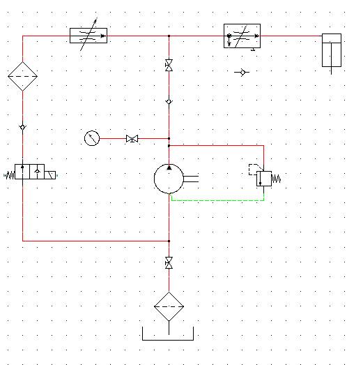
The rest of the hydraulic drawing consists of inserting a Pressure Gauge and Check Valve at the left side of the pump and then inserting devices (Cylinder; Restrictors; Filter; Check valve and 2-ways valve) along the top of the drawing.
Insert components
- Click

 .
Find
.
Find
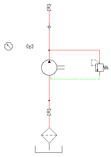
- In the Insert Component: Hydraulic Symbol dialog box, click Meters.

- In the Hydraulic: Meters dialog box, click Pressure Gauge.

- Respond to the prompts as follows:
Specify insertion point:
Select to place the pressure gauge to the far left (and slightly above) of the pump
- In the Insert/Edit Component dialog box, specify:
Component Tag: MTR1
Description: Line 1: Pressure Gauge
Click OK.
- Click
.
Find
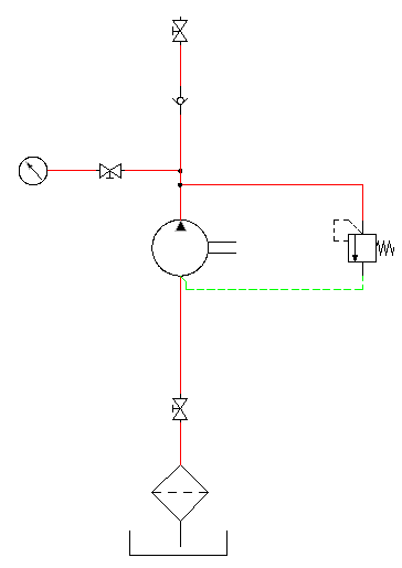
- In the Insert Component: Hydraulic Symbol dialog box, deselect the Vertical check box.
- In the Insert Component: Hydraulic Symbol dialog box, click General Valves.

- In the Hydraulic: General Valves dialog box, click Shut Off Valve Open.

- Respond to the prompts as follows:
Specify insertion point:
Select to place the valve to the right of the pressure gauge
- In the Insert/Edit Component dialog box, click OK.
- Set the wire layer to RED_20.
- Click
. Find
- Respond to the prompts as follows:
Specify wire start or [wireType/X=show connections]:
Select the right connection point on the pressure gauge
Specify wire end or [Continue]:
Drag the pipe to the right and click the left connection point on the valve
Specify wire start or [Scoot/wireType/X=show connections]:
Select the right connection point on the valve
Specify wire end or [Continue]:
Drag the pipe to the right and click the vertical pipe, right-click
- Click
. Find
- Insert and place the devices listed as shown in the following illustration. In the Insert/Edit Component dialog box, click OK after each insertion.
Note: You can also insert the vertical or horizontal pipes first and then insert the components onto the pipe, one by one.
Icon Symbol to Insert 
2 Way Valves
(insert as Vertical symbol) Solenoid Spring Return -1

General Valves
Checkvalve Flow Left (insert as a Vertical symbol)

Filters
Filter (insert as a Vertical symbol)

Restrictors
Restrictor with Variable Output Flow

Restrictors
By-Pass Flow Regulator with Variable Output Flow

Cylinders
Single Acting Single Ended Piston Rod
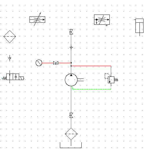 Tip: Align the components horizontally and vertically using the Align tool to make inserting the pipes easier.
 - Click
. Find
- Connect the pipes from one control device to another as illustrated.
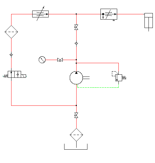
- Click
. Find
- In the Insert Component: Hydraulic Symbol dialog box, click General Valves.
- In the Hydraulic: General Valves dialog box, click Checkvalve Flow Left.
- Respond to the prompts as follows:
Specify insertion point: Select to place the valve below the restrictor
- In the Insert/Edit Component dialog box, click OK.
- Click
. Find
- Connect the pipes as shown.
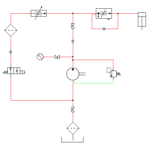
The hydraulic schematic diagram is complete.
If you want to create a pneumatic drawing, use the Insert Pneumatic Components tool on the Schematic tab
Insert Components panel. Refer to the pneumatic demo drawing file (Demo03.dwg) in the Extra Library Demo project.