
Have you ever needed to place evenly spaced objects along another object, or place objects at specific intervals along another object? Let's say you need to place several evenly spaced light posts along a street. To complete the task, you evaluated the length of the street, did some math, and then figured out how far apart each light post needs to be. But there's a faster way! Let's take a look at how to use DIVIDE and MEASURE to divide an object equally or based on a specific interval, and place points or blocks along an object.
Set a Point Style
When we use the DIVIDE and MEASURE commands in this exercise, we'll create point objects along objects. Point objects are objects consisting of a single coordinate location that can be used as nodes or reference geometry for object snaps and relative offsets.
To get started, we'll want to make the point objects we create more visually noticeable. Let's change the point style using the PTYPE command, which sets the style and size of all point objects in the drawing. We don't need to do this step, but if we didn't, the points we create would be just a single pixel, which can be quite difficult to see.
- Click
Find
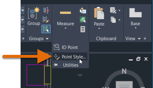
You can also enter PTYPE at the Command prompt.
- In the Point Style dialog box, choose the fourth point style option, and set the point size to 5 units.
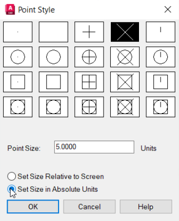
We can choose whether the size of the point object is determined by the size of the display screen, which means the size of the point will depend on how zoomed in we are when we create the point, or if it is set to an absolute size.
- Click OK.
DIVIDE command
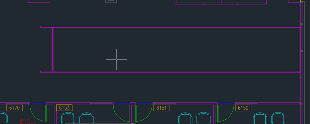
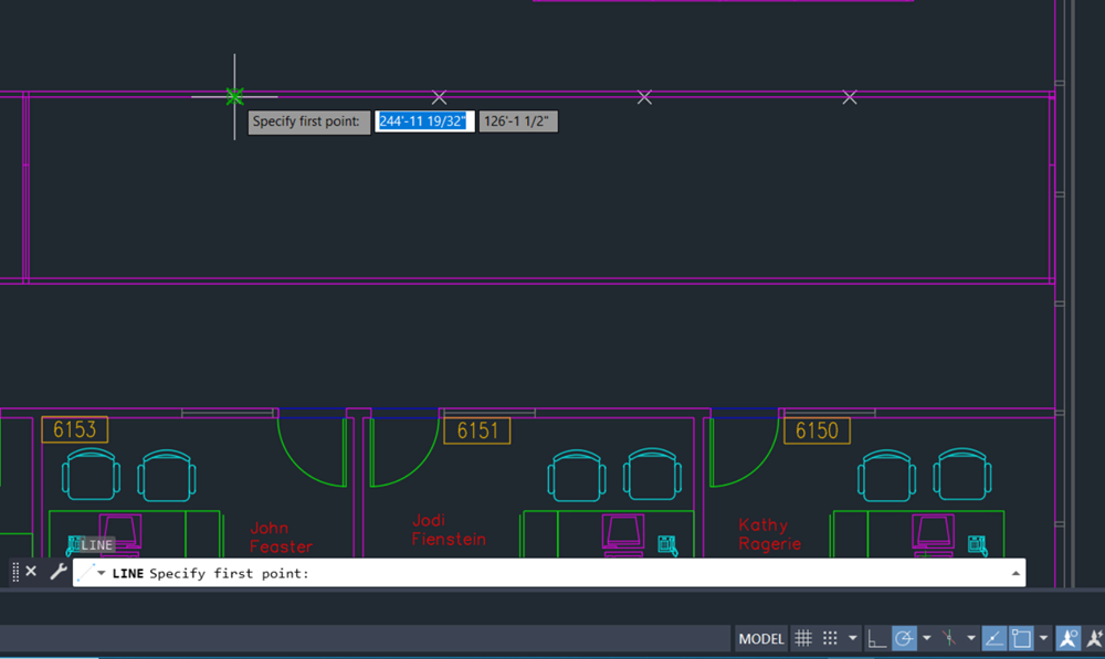
Suppose we want to add walls to create five office cubicles in the empty space between these walls. To re-create this exercise for yourself, you can use the Floor Plan Sample.DWG sample drawing and delete cubicles 6156 to 6162, or create a new drawing and simply draw a similarly shaped rectangle to represent the office walls.
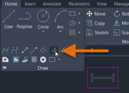
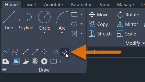
- Click
Find
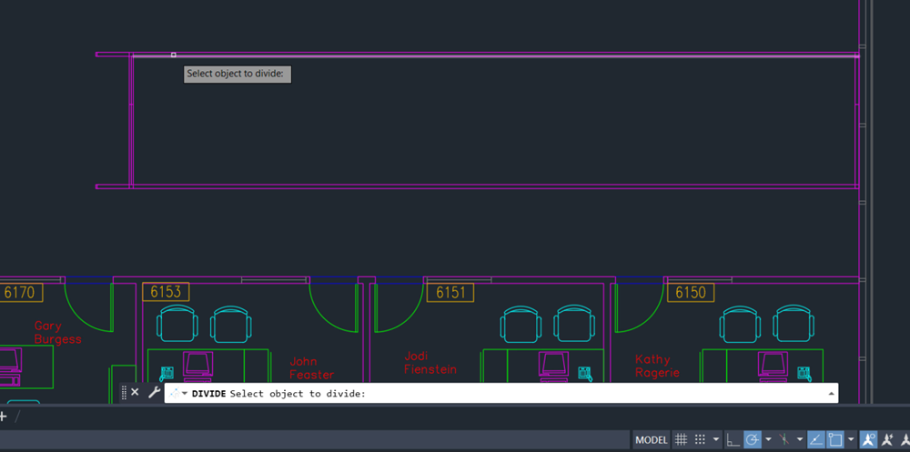
You can also enter DIVIDE at the Command prompt.
- Select the line to divide.
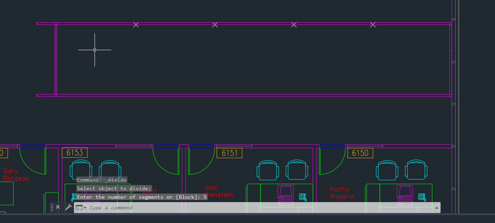
- Enter 5 for the number of segments.
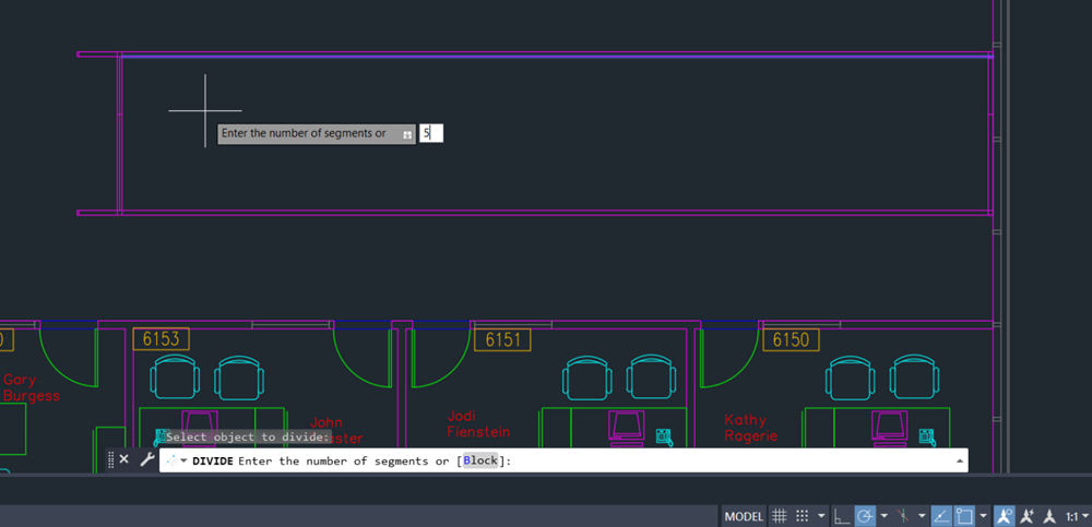
The line segment now has four points on it, marking it into five equal parts. It’s still just one line object. We didn’t break the line into four lines (we could use the BREAK or BREAKATPOINT commands for that), but instead we added four points on this object.
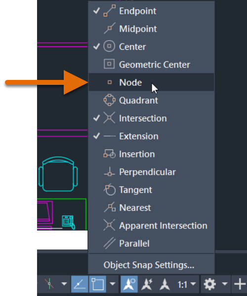
Now that the points are created, we’ll also want to make sure we have the Node Object Snap Mode turned on, so we can acquire those points.
- On the status bar, click Object Snap or press F3 to turn on Object Snap Mode.

When on, the Object Snap button has a blue background color.
- Right-click the Object Snap button and select the Node option, if it isn't already checked.
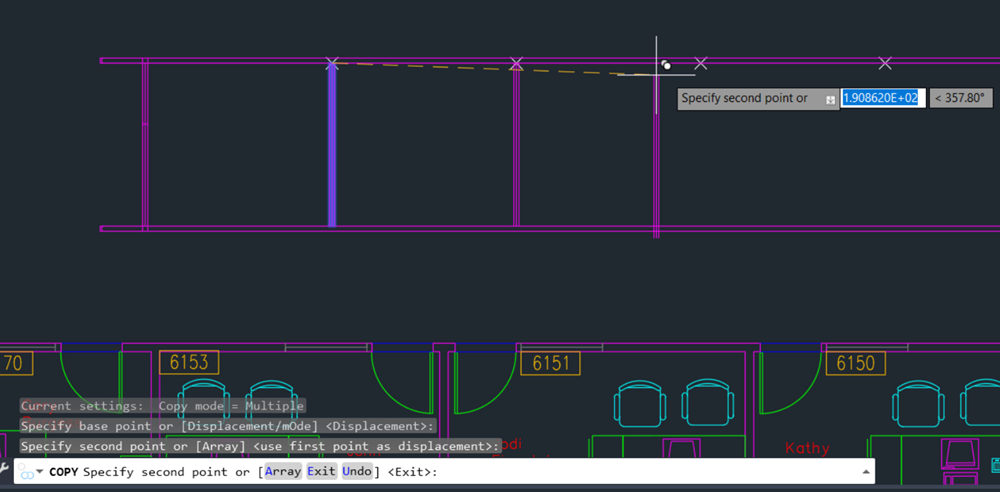
Now we can easily tell where our walls should go. Use the LINE command to create a wall, and then the COPY command to duplicate a wall where each point is located.
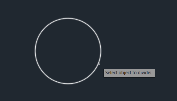
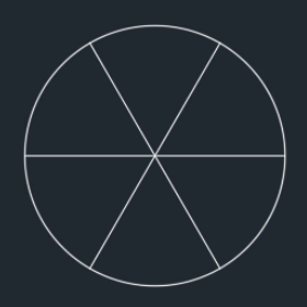
Let’s use the DIVIDE command again, but this time let’s divide a circle. Suppose we want to divide a circle into six equal “slices,” as shown here.

- Click Find
- Create a circle.
- Click
Find
You can also enter DIVIDE at the Command prompt.
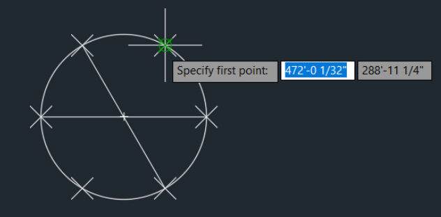
- Select the circle to divide.
- Enter 6 for the number of segments.
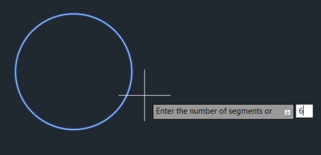
- Now, to finish the design, we can simply create three lines. Use the Node object snap and snap to the points on the circle to connect each point to its opposite point.
- When you’re finished, if you no longer want to see the point objects on the circle, you can turn them off. At the Command prompt, set
PDMODE to 0 to set point objects to display as a single pixel. Set PDMODE to 1 to hide point objects.
MEASURE command
MEASURE creates point objects or inserts blocks at measured intervals along an object. It works a lot like DIVIDE, except instead of inputting the number of segments to divide the object into, you instead input the distance between each point along the object.
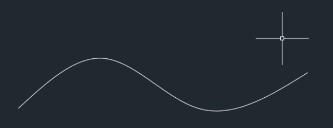
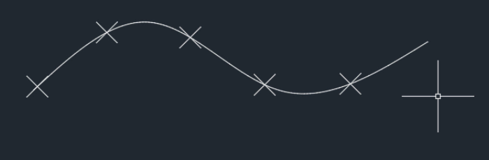
Let's try the MEASURE command. Suppose we wanted to add points to a spline that were 200 units apart.
- Click Find
- Create a spline, as shown here.
- Click
Find
You can also enter MEASURE at the Command prompt.
- Select the spline to measure.
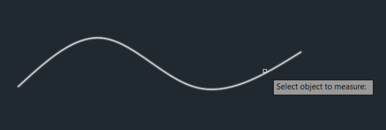
- Specify the length of each segment. This value is the space between each point object. The points are placed starting at the endpoint closest to the point that you used to select the object, and continue until no more points can fit along the object.
Place Blocks at Equal Intervals
So far, we’ve used DIVIDE and MEASURE to place points on objects, but you can also use the Block option to place blocks along the length or perimeter of an object. In the following example, we’ll use DIVIDE to place five evenly spaced blocks (in this case, trees) along a spline.
First, let's insert a block into the drawing from DesignCenter. In this example, we'll use the Trees - Imperial block from the Architectural - Imperial.dwg sample drawing, but you can also use any block of your own. To insert a block:
- If DesignCenter is not already open, click . Find
- On the DesignCenter toolbar, click Tree View Toggle.
- In the tree view, navigate to Sample\en-us\Dynamic Blocks\Architectural - Imperial.dwg.
- Expand the list under the drawing and click Blocks to display images of the block definitions in the drawing.
- Select the Trees - Imperial block and drag it into the drawing. This adds the block reference to the current drawing.
- Click Find
- Create a spline, as shown here.
- Click
Find
You can also enter DIVIDE at the Command prompt.
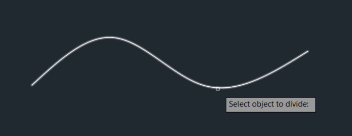
- Select the spline to divide.
- Enter
BLOCK at the Command prompt.
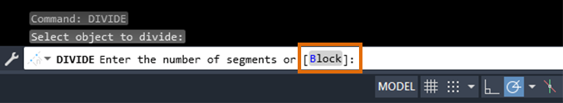
- Enter “Trees - Imperial” as the name of the block to insert.
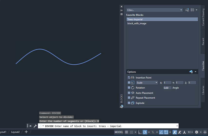
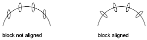
- Choose whether to align the block with the object. Enter
Yes to align the blocks according to the curvature of the selected object. Enter
No to align the blocks according to the current orientation of the user coordinate system.
- Enter the number of segments.

Summary
The DIVIDE and MEASURE commands, when used in combination with point styles and blocks, can save time while drafting. Hopefully, the techniques in this article help reduce your effort when you need to place objects equally or at specific intervals along an object.
Related Have You Tried Articles
- Have You Tried: The Status Bar. The status bar provides quick access to some of the most commonly used drawing aids and tools.
- Have You Tried: Associative Arrays. Arrays are amazingly flexible, supporting rectangular arrangements, polar arrangements, and objects arranged along a straight or curved path.
- Have You Tried: Calculate Area and Measure Distance. Accurate measurements in the drawing can save time and cost, and verify the feasibility of your designs.
Commands and System Variables for Divide and Measure
Here are some frequently used commands and system variables related to working with divide and measure.