
Slabs and roof slabs are AutoCAD Architecture 2025 toolset objects that you use to model floors, roof faces, and other flat surfaces where edge conditions need to be specified. The slab or roof slab object is a three-dimensional (3D) body bounded by a planar polygon (perimeter) of any shape, and has multiple edges. The object is defined by its perimeter, edge conditions, and style. Though they share many of the same properties, slabs and roof slabs represent separate style categories and tool types. For instance, you cannot apply the properties of a slab tool to an existing roof slab object.
Roof Slabs
A roof slab models a single face of a roof. Roof slab objects also differ from roof objects in that each roof slab is a separate entity with no direct connection to other entities. When you use multiple roof slabs to model an entire roof surface, you have more flexibility in editing the roof, but the combined topology (3D geometry) of the roof is not calculated automatically. For this reason, it is recommended that when you design complex roofs, you start with a roof object. Then, when the design is substantially complete, but you need more flexibility for customizing edges and other details, you can convert the roof to individual roof slabs.
While roof slabs do not dynamically interact with each other, they do allow significant control over the roof geometry. For example, you can trim roof slabs individually, extend them, and miter them with other roof slabs. You can also cut holes in roof slabs, add or subtract mass elements, and apply detailed fascia and soffit profiles to any edge at any angle and orientation. Like slabs, roof slabs are style-based, so you can apply design changes globally.
Methods of Creating Slabs/Roof Slabs
Using slab and roof slab tools, you can create slabs and roof slabs independently, or you can create them from existing objects, such as walls and polylines. Slabs and roof slabs created from other objects do not maintain a link to the original object.
Pitched roofs are usually designed by specifying a plate line and a slope angle. Roof slabs are designed so that you can use the same approach in laying them out. To add a roof slab, you simply specify two points and an angle.
If you have a traditionally designed roof created from a two-dimensional (2D) plan showing ridge, hip, and valley lines, you can trace over that plan with roof slabs, specifying the desired height and slope. From these values and the specified points, the software creates the correct three-dimensional (3D) model.
Slab/Roof Slab Bodies
The body of a slab or roof slab is an extrusion perpendicular to the plane of the perimeter and is defined by the following geometry:
- The perimeter of a slab or roof slab is a planar polygon defined by the X,Y,Z coordinates of its vertices.
- A slab or roof slab has 3 or more vertices, with the ability to add or remove vertices. Each pair of vertices defines an edge.
- The thickness of a slab or roof slab extrusion is specified either in the object style (when it has a fixed thickness) or for the individual object.
- The position of the slab or roof slab bottom, relative to its perimeter plane, is controlled by the thickness offset value in the style.
- The baseline of a slab or roof slab is defined by the first two points you select when defining the vertices.
- The slab or roof slab insertion point, by default, is the first point on the baseline. You can offset the baseline either horizontally or vertically from the insertion point to allow for precise alignment with walls or structural elements.
- A slab or roof slab has a slope (pitch), which you can specify either as an angle or as a rise-to-run ratio. If you change the slope, the slab or roof slab rotates around the slope pivot point.
- The pivot point is initially the first vertex of the baseline, but you can move it to any other point, either on or off the slab or roof slab. A small pyramid-shaped marker represents the pivot point.
- An imaginary line passing through a slab or roof slab at the perimeter line (in section) is called the slopeline. The slopeline aligns the slab or roof slab with the wall base height. The slopeline is the position of the slab or roof slab baseline relative to its bottom face. The value you enter for the thickness offset in the slab or roof slab style determines the distance between the slab or roof slab baseline and the bottom face of the slab or roof slab.
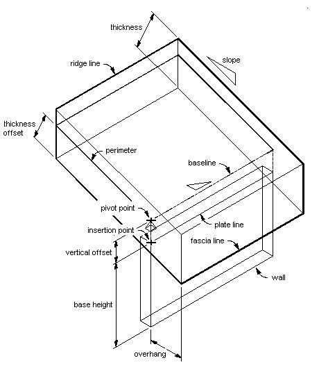
Geometry of a roof slab
Slab/Roof Slab Edges
The following parameters define a slab or roof slab edge:
- edge cut orientation (plumb or square)
- angle (relative to the orientation)
- edge style (fascia and soffit)
- overhang (defines the point at which the fascia begins)
You apply a fascia and soffit to slab or roof slab edges with styles that define edge conditions
- The fascia is defined by a profile, with its insertion point located at the top of the slab or roof slab edge. The local Y axis of the profile polyline aligns with the slab or roof slab edge angle.
- The soffit is also defined by a profile, with its insertion point positioned at the X and Y offsets from the fascia insertion point.
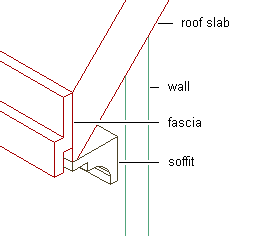
Roof slab with fascia and soffit components
Edge Control
You can customize each slab or roof slab edge individually, applying styles and making other adjustments as required by your design. A slab or roof slab edge style defines the fascia and soffit design from profiles that you create for these components. You can specify whether the style uses a fascia, a soffit, both, or neither. You also specify how the fascia and soffit are positioned relative to the slab or roof slab.
Slab and Roof Slab Styles
Slabs and roof slabs have their own distinct style categories in which individual styles specify the default properties for specific types of slabs or roof slabs. These properties include dimensions, edge styles for the fascia and soffit, and entity properties for layer, color, and linetype. Slab and roof slab styles allow you to use a different edge style for each edge.
Materials in Slabs and Roof Slabs
You can assign materials to a slab or roof slab. For example, a floor slab can be assigned a material representing tiles with concrete edges. These materials are displayed in wireframe or rendered views. Materials have specific settings for individual components of slabs or roof slabs, such as the body, fascia and soffit.
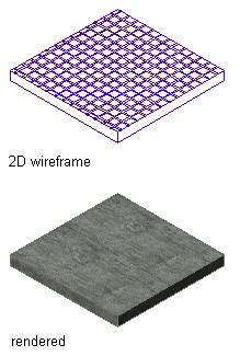
Slab appearance in different views
AutoCAD Architecture 2025 toolset provides predefined materials for common design purposes. These materials contain settings for slabs or roof slabs that you can use as provided or modify for special designs. You can also create materials from scratch. If you create a material to use only for slabs, name it accordingly; for example, Slab—Ceramic Tile or Slab Edge—Concrete. This will help in organizing your material definitions.
Editing Tools
In addition to the control provided by slab or roof slab styles and edge styles, AutoCAD Architecture 2025 toolset includes a variety of tools that let you edit slabs and roof slabs to fit unique conditions. For example, you can add holes to slabs for structures such as chimneys and vent pipes. You can also use roof slabs to create dormers.