
12. Organize and Output a Design with Layouts (AutoCAD Foundations)
Once you have completed a design, you will often need to share the design with members on and outside of your team. Sharing a design often involves one of two things: providing access to the original drawing file or outputting the drawing to a different format (physical hard copy or electronic file). Outputting a drawing to a physical hard copy or electronic file is done through a process known as plotting. Plotting a drawing is the same as printing a document or spreadsheet. For this topic, the terms plot and print are interchangeable.
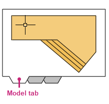
As you know, you create the geometry of your design in model space which is represented by the Model tab. While a design can be plotted from model space, it is more common to use named layouts.
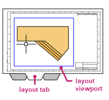
A named layout, also known as paper space, is used to organize one or more views of your design created in model space. You can think of a named layout as the digital equivalent to a sheet of paper. Views of a design are presented on a layout with the use of viewports. A layout viewport not only controls which part of a design in model space to display but also controls the scale and visibility of the geometry.
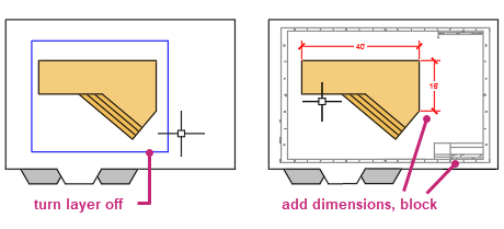
In addition to viewports, named layouts also commonly contain a title block and annotation (text, tables, and dimensions).
Plotting a drawing is performed with the Plot dialog box. The Plot dialog box allows you to:
- Choose the printer or plotter device to use
- Set the paper size on and orientation at which the design or layout should be plotted
- Define the area of the design or layout to plot: extents, named view, window, or drawing limits
- Set the offset or center the area to plot
- Set the scale of the geometry to plot
- Control the appearance of geometry by assigning a plot style and shaded viewport options
- Enable miscellaneous plot options
The following video demonstrates some of the learning objectives covered in this topic:
Learning Objectives
Prerequisites
You should know how to do the following before continuing:
- Create, open, save, and view drawings
- Work with commands
- Create basic 2D objects (lines and circles)
- Select, modify, and duplicate objects
- Define and insert blocks
Prepare for the Exercises
To follow along with the exercises in this topic, download the ZIP file containing the sample drawings.
![]() Download: Sample drawing files used for the following exercises
Download: Sample drawing files used for the following exercises
The ZIP file contains all drawings used for the exercises and only needs to be downloaded once. Keep the ZIP file to restore the original state of the sample drawings.
Plot an Area of a Design from Model Space
Model space is where you create the geometry for your design. Then you typically use named layouts to organize that design to be plotted. While named layouts are the preferred way to organize and plot your designs, you can plot the extents or an area of a design from model space. Plotting from model space can an efficient way to have a team member or client review and mark up a specific area of a design.
Try It: Plot a Specific Area in Model Space
Plot an area of model space in the drawing.
- On the Quick Access toolbar, click Open.Find
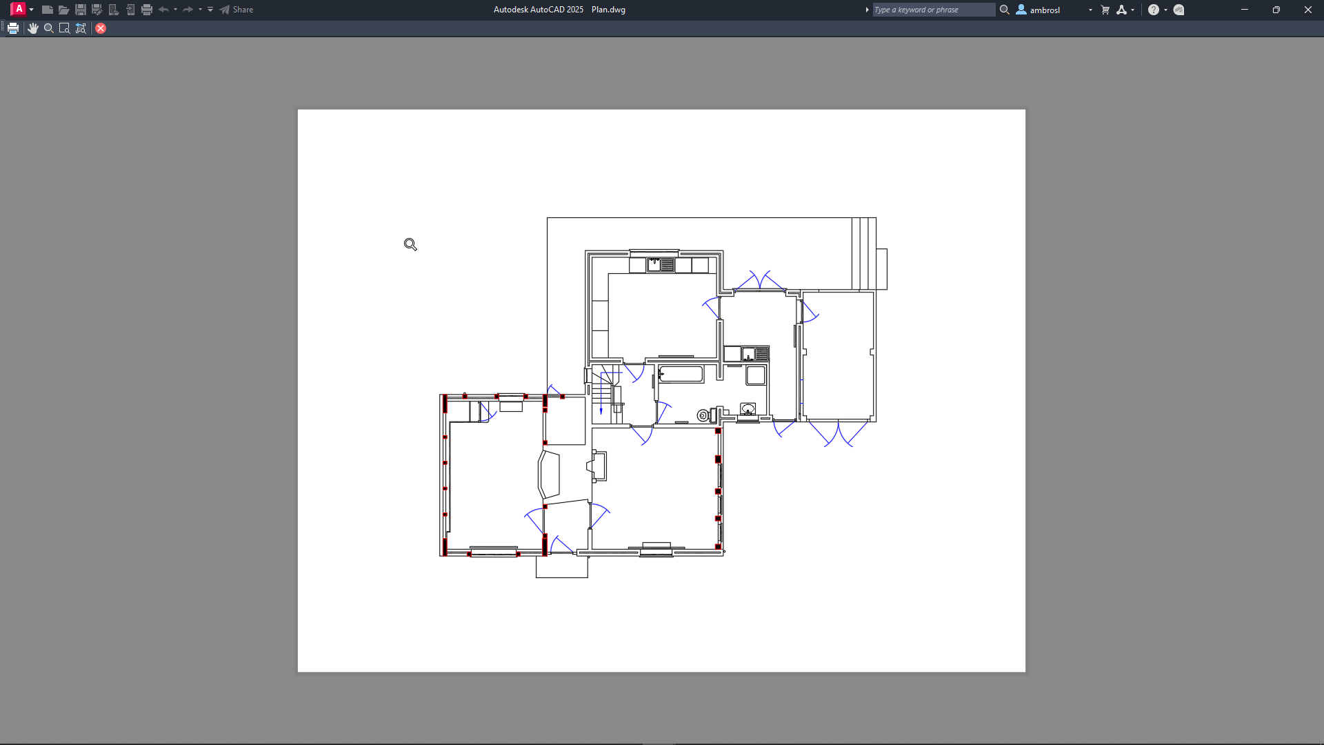
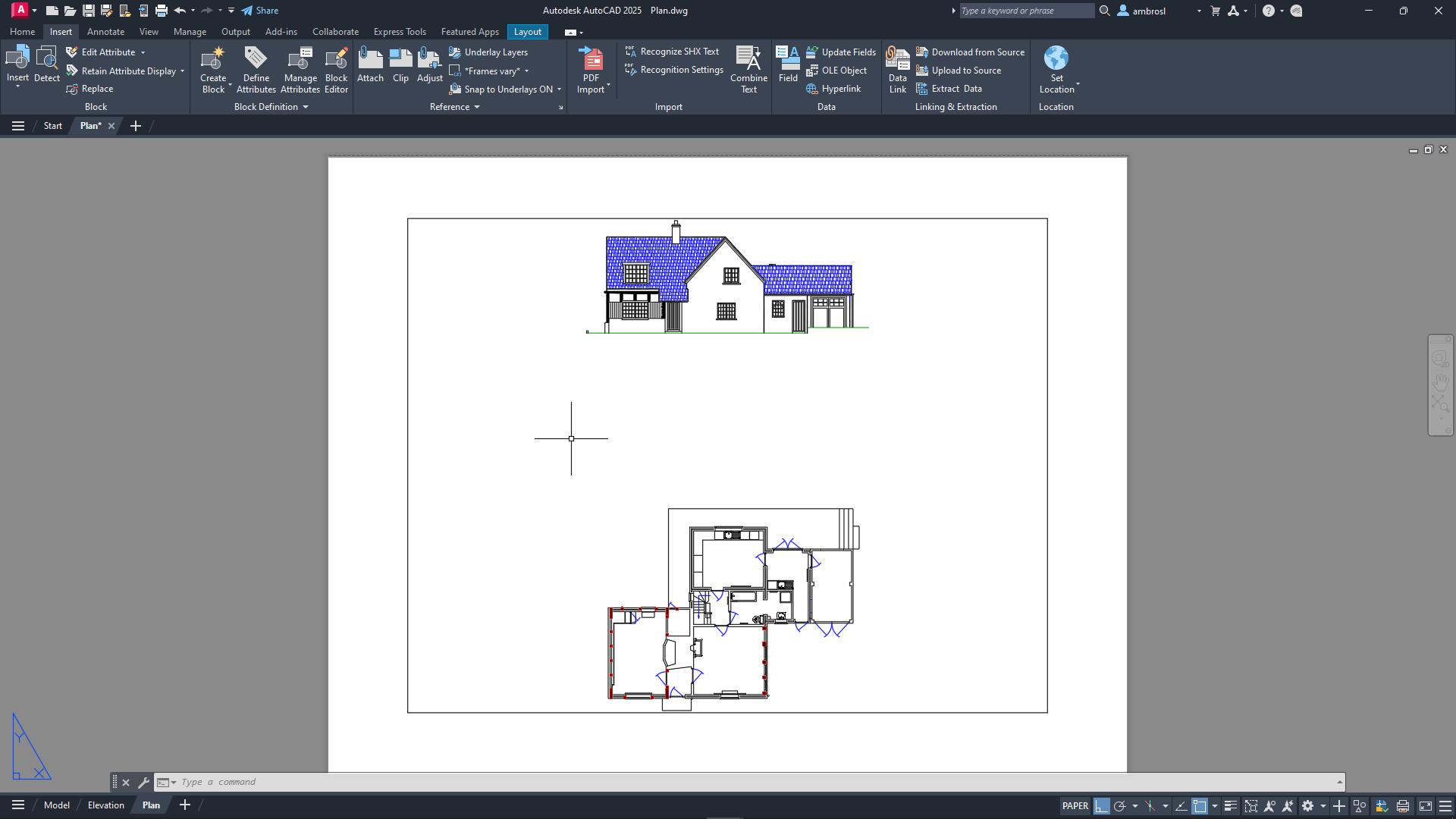
In the Select File dialog box, browse to the sample files you previously downloaded and select the Plan.dwg file. Click Open.
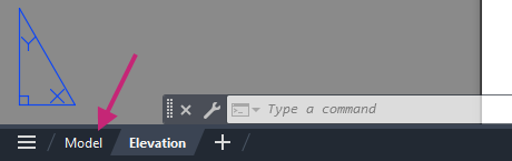
On the layout tabs, below the drawing window, click the Model tab.
- On the Quick Access toolbar, click Plot.Find
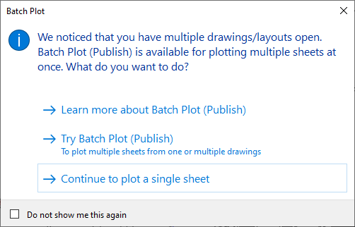
If the Batch Plot task dialog box is displayed, click Continue to Plot a Single Sheet.
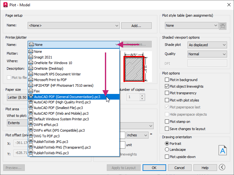
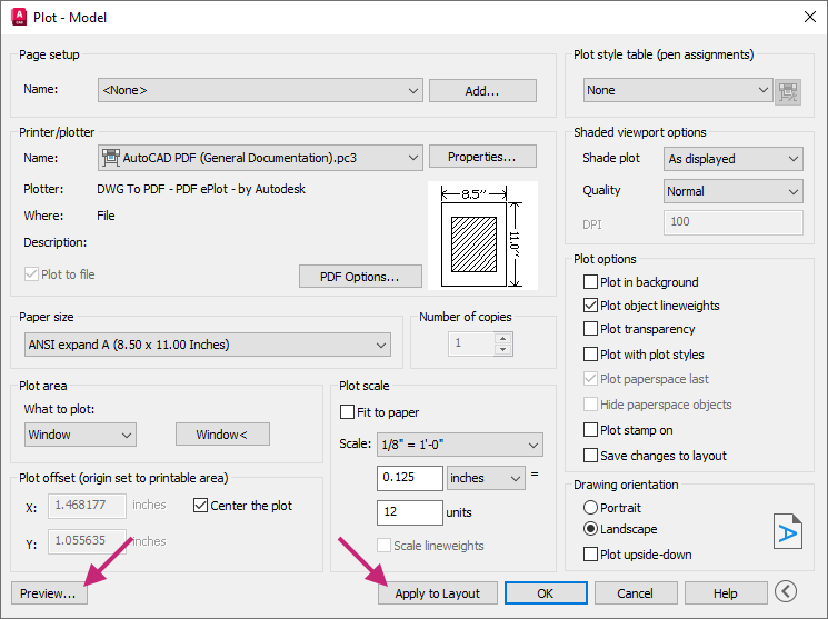
In the Plot dialog box, under Printer/Plotter, click the Name drop-down list and choose AutoCAD PDF (General Documentation).pc3.
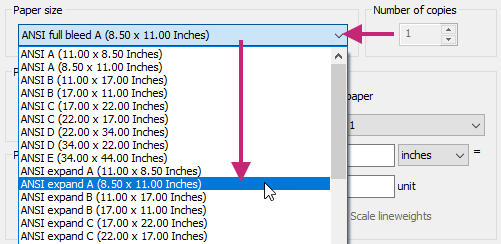
Under Paper Size, click the drop-down list and choose ANSI expand A (8.50 x 11.00 Inches).
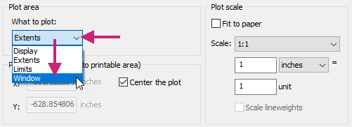
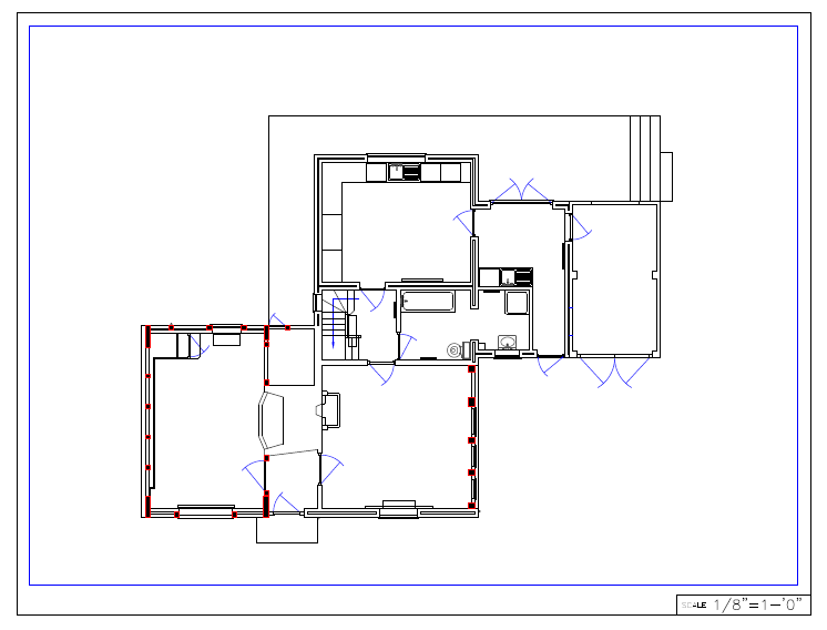
Under Plot Area, click the What to Plot drop-down list and choose Window.
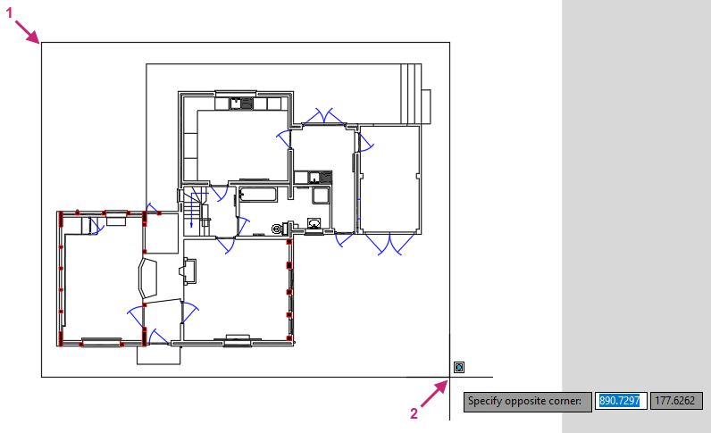
Click the Window button and specify two points to define a window around the floor plan.
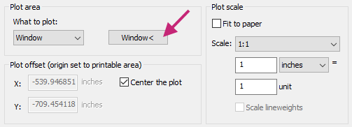
Under Plot Offset (Origin Set to Printable Area), click Center the Plot.
The checkbox should be checked.
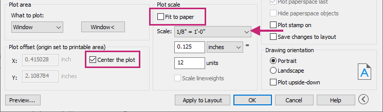
Under Plot Scale, clear Fit to Paper, and then click the Scale drop-down list and choose 1/8" = 1'-0".
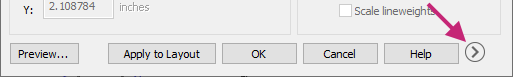
If the dialog box is not expanded, click More Options.
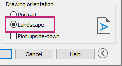
Under Drawing Orientation, click Landscape.
Click Apply to Layout to save the changes made to the plot settings and then click Preview.
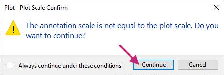
If the Plot - Plot Scale Confirm message box is displayed, click Continue.
In the Preview window, click and drag to increase and decrease the size of the preview. Right-click and use the shortcut menu to switch between the Zoom and Pan tools.
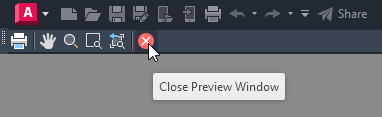
Press Esc or click Close Preview Window to return to the Plot dialog box, and then click OK.
If the Plot - Plot Scale Confirm message box is displayed, click Continue.
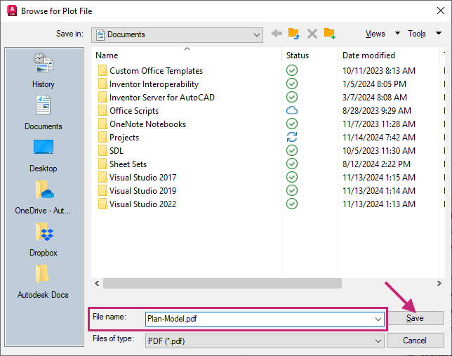
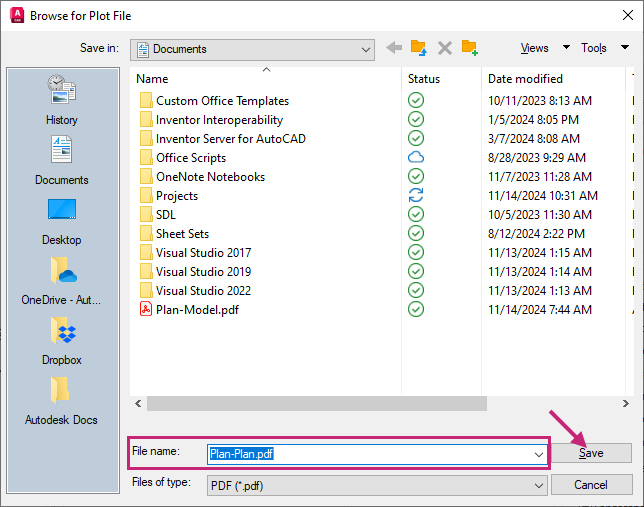
In the Browse to Plot File dialog box, browse to the Documents folder or a different location, and then provide a filename for the PDF file. Click Save.
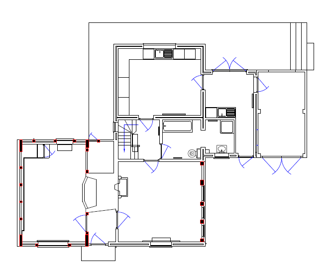
Review the PDF file if it automatically opens, otherwise open and review the file from Windows File Explorer.
Return to AutoCAD.
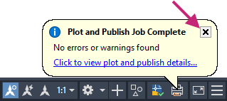
On the status bar, close the Plot and Publish Job Complete notification.
- On the Quick Access toolbar, click Save.Find
Use Layouts to Organize a Design for Output
A layout is used to organize a design for output. Viewports are added to display and scale the geometry in model space along with a title block and annotation. Annotation can include
- General notes and tables
- Dimensions
- View-specific label and callout blocks
- Plot stamp
Try It: Create a New Layout and Modify Page Setup
Create a new layout and modify the page setup that will be used to plot the layout.
If you closed the Plan.dwg file from the previous exercise, reopen the file.
On the layout tabs, below the drawing window, click the + (New Layout) button.
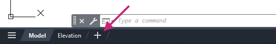
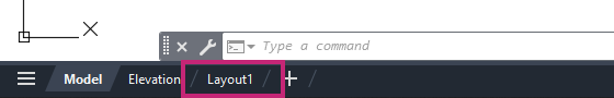
A new layout named Layout1 is added.
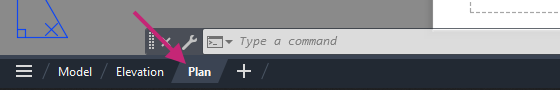
Right-click over the Layout1 layout tab and choose Rename. Type Plan and press Enter.
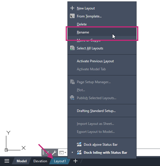
The layout tab is renamed.
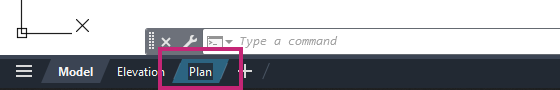
Click the Plan layout tab to make it current.
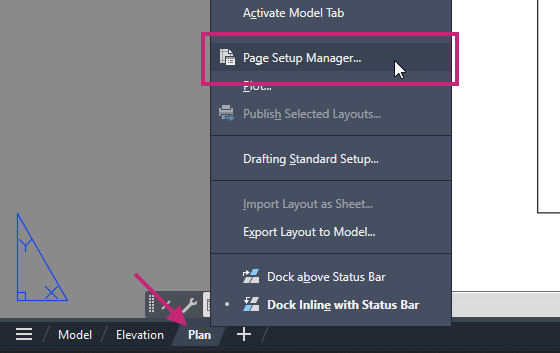
- Right-click over the Plan layout tab and choose Page Setup Manager.Find
In the Page Setup Manager, from the Page Setups list, select *Plan* and click Modify.
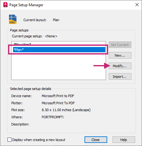
In the Page Setup dialog box, do the following:
Under Printer/Plotter, click the Name drop-down list and choose AutoCAD PDF (General Documentation).pc3.
Under Page Setup, click the drop-down list and choose ANSI expand A (8.50 x 11.00 Inches).
Under Plot Area, click the What to Plot drop-down list and choose Layout.
Under Plot Scale, click the Scale drop-down list and choose 1:1.
Under Drawing Orientation, click Landscape.
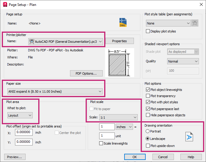
Click OK to save the changes and exit the Page Setup dialog box.
In the Page Setup Manager dialog box, click Close.
- On the Quick Access toolbar, click Save.Find
Try It: Add a Title Block
Insert a title block on the new layout to provide information about the design information represented when the layout is plotted.
Continue with the Plan.dwg file from the previous exercise: Try It: Create a New Layout and Modify Page Setup.
If the Plan layout tab is not current, click the layout tab now.
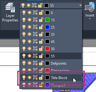
On the ribbon, click Home tab > Layers panel > Layers drop-down list and choose Title Block.
- Click View tab > Palettes panel > Blocks.Find
On the Blocks palette, Current Drawing tab, click Letter (landscape).
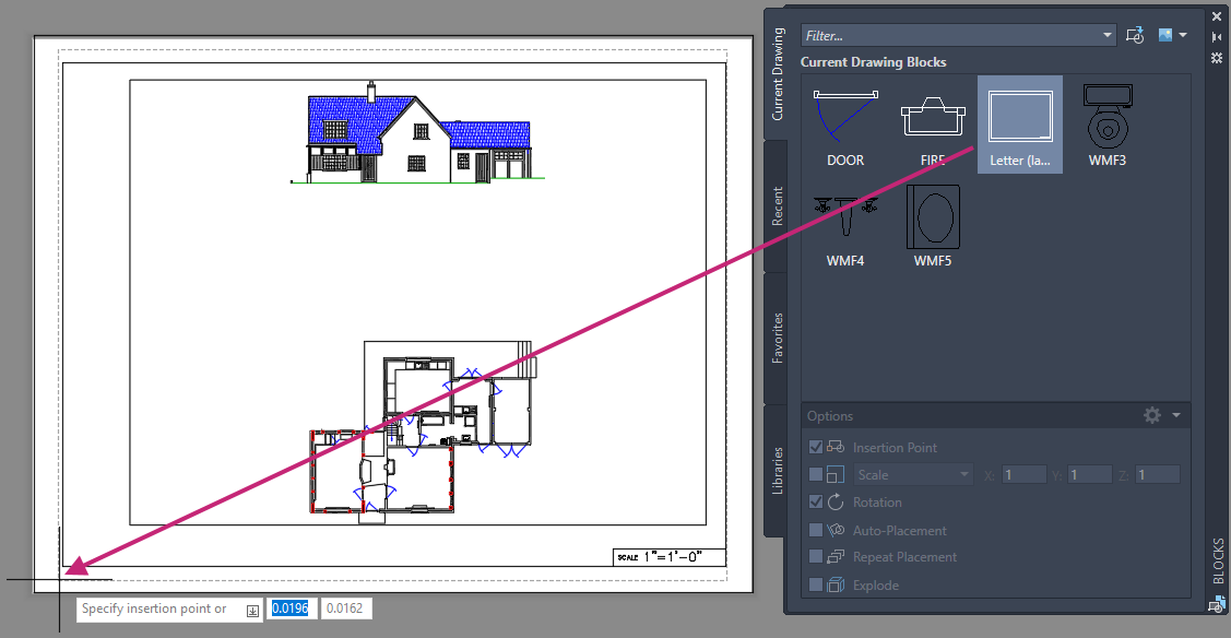
At the Specify insertion point or [Basepoint/Scale/X/Y/Z/Rotate]: prompt, enter 0,0.
At the Specify rotation angle <0.00>: prompt, press Enter to accept the default value.
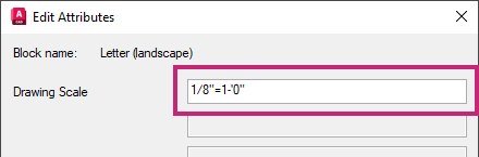
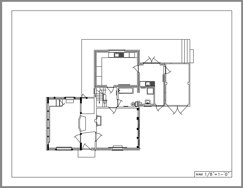
In the Edit Attributes dialog box, Drawing Scale text box, replace the current text with 1/8"=1-'0" and click OK.
- On the Quick Access toolbar, click Save.Find
Create Viewports to Control the Area of a Design on a Layout
Layouts are the digital equivalent to a sheet of paper and to display your design on a layout you need to create viewports. Layout viewports are created on a layout tab to display a scaled view of an area in model space. Once created, you can define which area of model space is displayed and control the visibility of layers for the viewport. Each viewport can display different areas of model space and have different layers that are visible. When a layout viewport is selected, you can change its size, location, and scale of the model space view using the grips that are displayed.

The following points summarize the relationship of layout viewports and model space:
The majority of the objects of your designs are created in model space on the Model tab.
For any significant editing of your design, use the Model tab.
To display and scale one or more views of model space on a layout, you create layout viewports.
The visibility of objects in a layout viewport are controlled by enter model space through the viewport. After entering model space, you can adjust the area of model space visible and control the visibility of layers in each layout viewport.
To create correctly scaled dimensions, you can enter model space through the viewport and then dimension the objects.
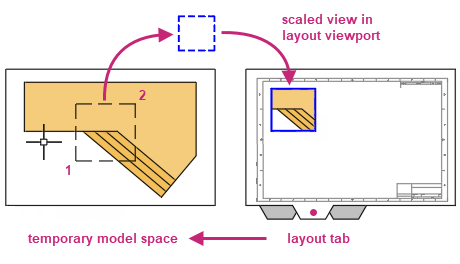
When on a layout tab, you can enter the model space of a layout viewport by double-clicking within the its boundary. The boundary of the layout viewport is thickened once model space is activated. Double-clicking outside of a layout viewport's boundary returns you to paper space.
Try It: Create a Layout Viewport
Create a viewport on the previously created named layout, Plan layout, to control which model space objects are to be plotted.
Continue with the Plan.dwg file from the previous two exercises: Try It: Create a New Layout and Modify Page Setup and Try It: Add a Title Block.
If the Plan layout tab is not current, click the tab now.
Select the layout viewport inside of the title block and press Delete.
Tip:Selecting objects and then pressing the Delete key is a shortcut to using the ERASE command which can be started from the ribbon by clicking Home tab > Modify panel > Erase.
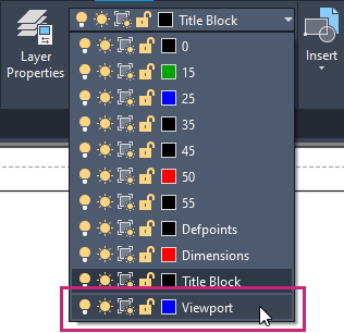
On the ribbon, click Home tab > Layers panel > Layers drop-down list and choose Viewport.
- Click Layout contextual tab > Layout Viewports panel > Create Viewport drop-down menu > Rectangular.Find
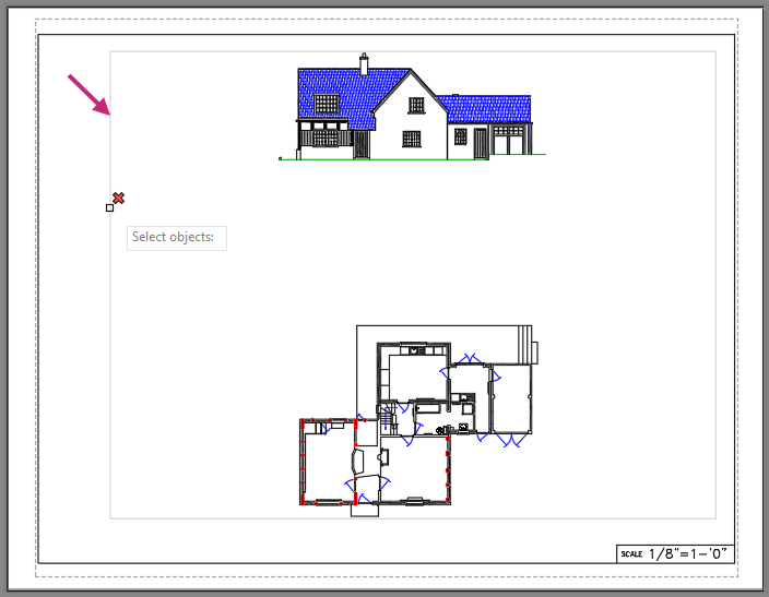
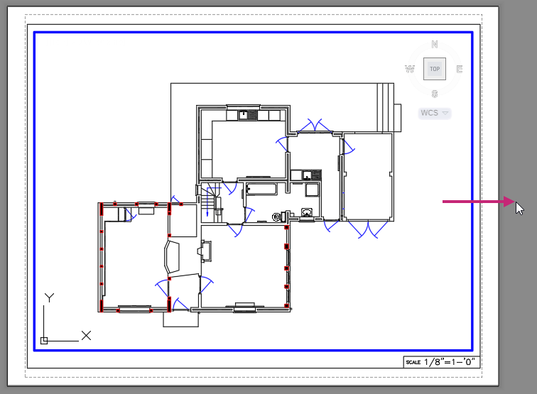
At the Specify corner of viewport: prompt, specify a point (1) inside of and towards the upper-left corner of the title block.
Tip:If running object snaps are enabled, press F3 to turn off running object snaps. The F3 key is a shortcut for clicking the Snap Cursor to 2D Reference Points button on the status bar.
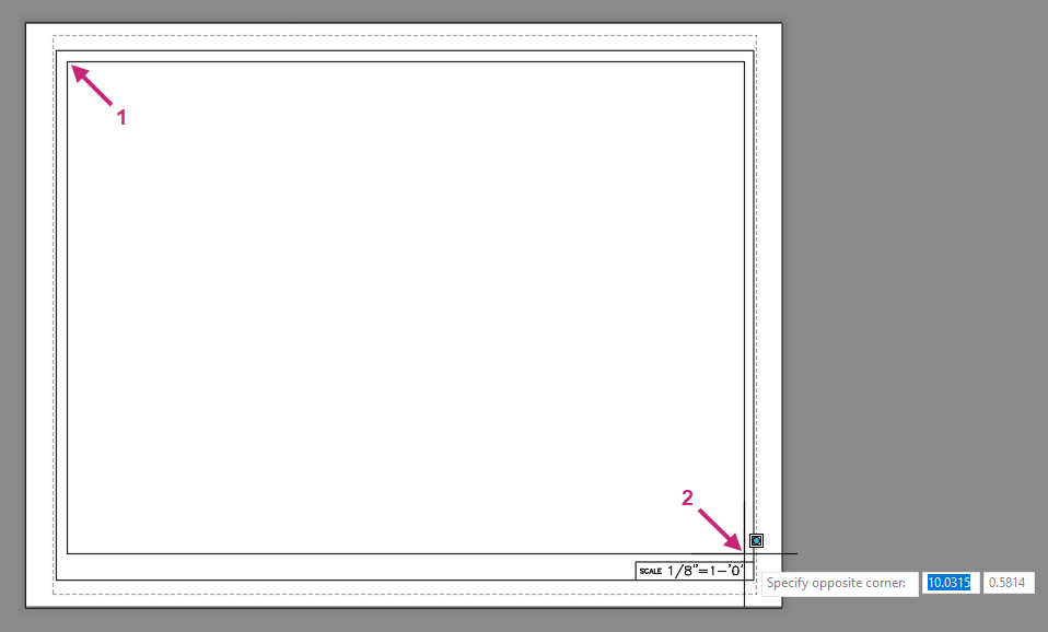
At the Specify opposite corner: prompt, specify a point (2) inside of and towards the lower-right corner of the title block.
The new layout viewport is created on the Viewport layer.
Double-click inside of the new layout viewport to enter model space.
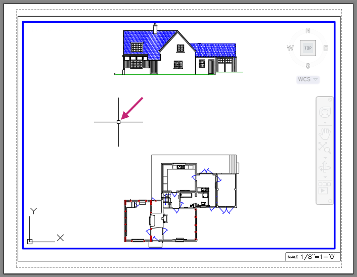
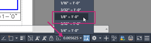
- On the status bar, click the Viewport Scale drop-down list and choose 1/8"=1'-0".Find
While in model space of the layout viewport, pan to center the floor plan.
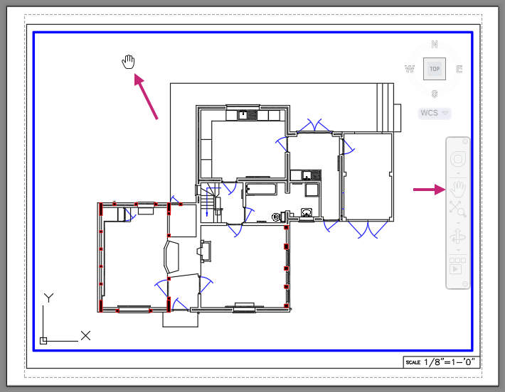
Press Esc to end any active navigation command.
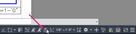
- On the status bar, click Viewport Lock.Find
The layout viewport is now locked and changes cannot be made to the view of model space without first unlocking the layout viewport. When a layout viewport is locked, focus is temporally switched to paper space while trying to change the view of model space.
Double-click outside of the layout viewport to return to paper space of the layout.
- On the Quick Access toolbar, click Plot.Find
If the Batch Plot task dialog box is displayed, click Continue to Plot a Single Sheet.
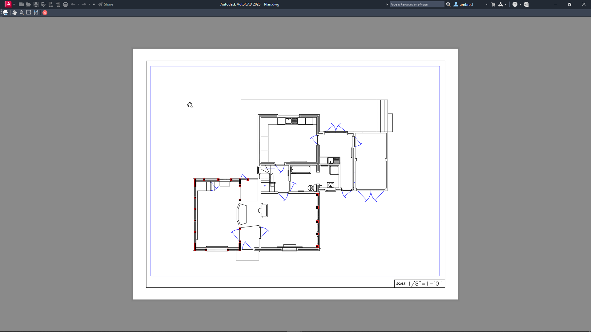
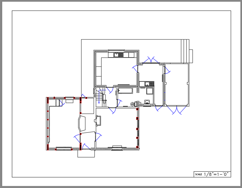
In the Plot dialog box, click Preview.
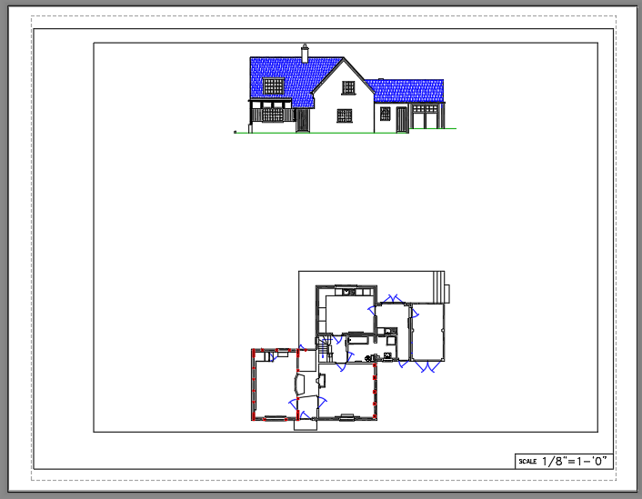
The layout is previewed using the plot settings previously set as part of the page setup defined by following the steps in the Try It: Create a New Layout and Modify Page Setup exercise.
In the Preview window, click and drag to increase and decrease the size of the preview. Right-click and use the shortcut menu to switch between the Zoom and Pan tools.
Press Esc or click Close Preview Window to return to the Plot dialog box, and then click OK.
In the Browse to Plot File dialog box, browse to the Documents folder or a different location, and then provide a filename for the PDF file. Click Save.
Review the PDF file if it automatically opens, otherwise open and review the file from Windows File Explorer.
Return to AutoCAD.
On the status bar, close the Plot and Publish Job Complete notification.
- On the Quick Access toolbar, click Save.Find
Control the Appearance of Objects During Plotting
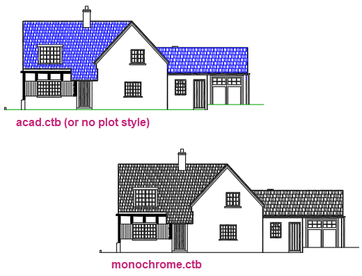
Layers are used to organize and control the appearance of objects on-screen, but when plotting you can override how objects look with plot styles. Plot styles provide information about how colors, linetypes and lineweights are handled when plotting. Colors that look good on-screen might not be suitable for a physical hardcopy or electronic file, so this is when you would want to use plot styles. For example, you might want to create a drawing with many colors to visually distinguish different objects, but when plotting the drawing you might want it to be monochrome.
Drawings can use one of two types of plot styles: color-dependent and named. Color-dependent plot styles are stored in CTB files and are used to map on-screen colors to specific colors along with linetypes and lineweights during plotting. Named plot styles are stored in STB files and must be assigned to individual objects or layers. Color-dependent plot styles are the most common of the two types used, and both have advantages and disadvantages. When you create a new drawing, the type of plot style to use is established.
Many drawings commonly use color-dependent plot styles, but its best to check with your company's or client's CAD standards to verify which should be used.
Try It: Assign a Plot Style Table
Assign a plot style table to a layout to control how objects appear when plotted.
Continue with the Plan.dwg file from the previous exercise: Try It: Create a Layout Viewport.
If the Plan layout tab is not current, click the tab now.
- On the Quick Access toolbar, click Plot.Find
If the Batch Plot task dialog box is displayed, click Continue to Plot a Single Sheet.
In the Plot dialog box, click Preview.
Notice some objects are displayed in color.
Close the Preview window.
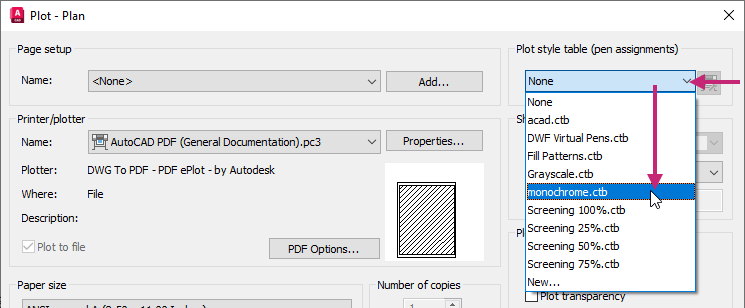
If the Plot dialog box is not already expanded, click More Options.
Under the Plot Style Table (Pen Assignments) section, click the Plot Style Table drop-down list and choose monochrome.ctb.
In the Plot dialog box, click Preview.
Notice all objects are now displayed in Black only rather than based on the color of their assigned layers or color overrides.
Close the Preview window.
In the Plot dialog box, click Apply to Layout and then click Cancel.
The change to the Plot Style Table setting is saved and the Plot dialog box is closed.
- On the Quick Access toolbar, click Save.Find
Summary
Plotting and printing a drawing allow you to share designs with members on and outside of your team. Layouts and layout viewports are used to organize views of the design in model space, while plot styles can help control how your designs look in physical hardcopy or electronic file.
Related Commands
| Command | Description |
|---|---|
| LAYOUT | Creates and modifies drawing layouts. |
| MSPACE | In a layout, switches from paper space to model space in a layout viewport. |
| MVIEW | Creates and controls layout viewports. |
| PLOT | Plots a drawing to a plotter, printer, or file. |
| PLOTSTYLE | Controls the named plot styles that are attached to the current layout and can be assigned to objects. |
| PSPACE | In a layout, switches from model space in a layout viewport to paper space. |