
6. Create Objects with Precision and Accuracy (AutoCAD Foundations)
Geometry and dimensions need to be placed precisely within your drawings to ensure accuracy when manufactured or built. When you create and modify objects, the dimensions and coordinates of those objects should match their real-world counterparts being modeled.
There are several precision features available when creating and modifying objects, including:
Coordinate entry. Specify a location by its Cartesian or polar coordinates, either absolute or relative.
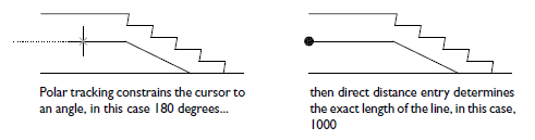
Polar tracking. Snap to the closest preset angle and specify a distance along that angle.
Locking angles. Lock to a single specified angle and specify a distance along that angle.
Direct distance entry. Locate the next point at a specified distance in the direction of your cursor.
Object snaps. Snap to precise locations on existing objects, such as an endpoint of a polyline, the midpoint of a line, or the center point of a circle.
Grid snaps. Snap to increments in a rectangular grid.
The most frequently used precision features are coordinate entry, locking angles, direct distance entry, and object snaps.
The following video demonstrates some of the learning objectives covered in this topic:
Learning Objectives
- Prerequisites
- Prepare for the Exercises
- Enter Coordinate Values
- Use Cartesian and Polar Coordinates
- Draw with Absolute Cartesian Coordinates
- Draw with Relative Cartesian Coordinates
- Draw with Polar Coordinates
- Use Direct Distance Entry
- Lock Angular Cursor Movement
- Ortho Mode
- Polar Tracking
- Snap to Precise Points on Objects
- AutoSnap Marks of Common Object Snaps
- Use Single Object Snaps
- Set Running Object Snaps
- Summary
- Related Commands
Prerequisites
You should know how to do the following before continuing:
- Create, open, save, and view drawings
- Work with commands
- Create basic 2D objects (lines and circles)
Prepare for the Exercises
To follow along with the exercises in this topic, download the ZIP file containing the sample drawings.
![]() Download: Sample drawing files used for the following exercises
Download: Sample drawing files used for the following exercises
The ZIP file contains all drawings used for the exercises and only needs to be downloaded once. Keep the ZIP file to restore the original state of the sample drawings.
Enter Coordinate Values
Coordinates represent locations in your drawing. When a command prompts you for a point, you can use the cursor to specify a point in the drawing area or enter coordinate values.
Use Cartesian and Polar Coordinates
In two-dimensional space, you specify points on a plane resembling a flat sheet of grid paper. You can enter two-dimensional coordinates as either Cartesian (X,Y) or polar (distance<angle) coordinates.
Cartesian coordinate. Locates an absolute point measured from two perpendicular lines that represent the X- and Y-axis. The X value specifies horizontal distance, and the Y value specifies vertical distance. For example, the coordinate (5,3) represents a point 5 units along the X-axis and 3 units along the Y-axis. The origin (0,0) indicates where the two axes intersect.
Polar coordinate. Locates a point at a known distance and angle from the origin (0,0). For example, 5<30 specifies a point that is a distance of 5 units from the origin (0,0) and at a 30-degree angle from the X-axis.
You can use absolute or relative values with each method. Absolute coordinate values are based on the origin (0,0). Relative coordinate values are based on the last point specified.
When you enter coordinates, you don't enter them with parentheses.
Draw with Absolute Cartesian Coordinates
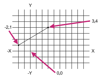
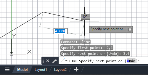
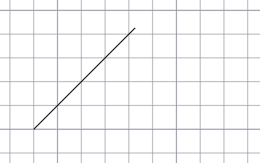
Use absolute Cartesian coordinates when you know the precise X and Y values of a point. For example, the line in the following illustration begins at an X value of -2 and a Y value of 1 for a coordinate value of (-2,1), and ends at (3,4).
Try It: Create a Line Using Absolute Cartesian Coordinates
Draw a line between two absolute coordinate points.
- On the Quick Access toolbar, click New.Find
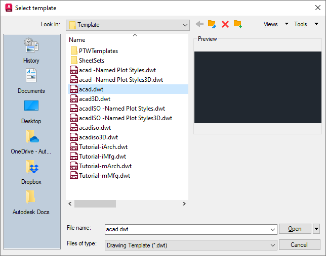
In the Select Template dialog box, select the acad.dwt drawing template file and click Open.
A new drawing is created based on the acad.dwt drawing template.
- On the ribbon, click Home tab > Draw panel > Line.Find
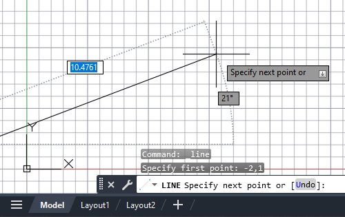
At the Specify first point: prompt, enter #-2,1.
The line starts off-screen because because it starts at a -2 X-coordinate value.
 Tip:
Tip:After you type a comma within a coordinate value, focus advances to the next dynamic tooltip. Pressing the Tab key allows you to cycle through the dynamic tooltips and re-enter a value.
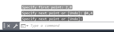
At the Specify next point or [Undo]: prompt, enter #3,4.
The line is drawn from -2,1 to 3,4.
At the Specify next point or [Undo]: prompt, press Enter or the Spacebar to end the command.
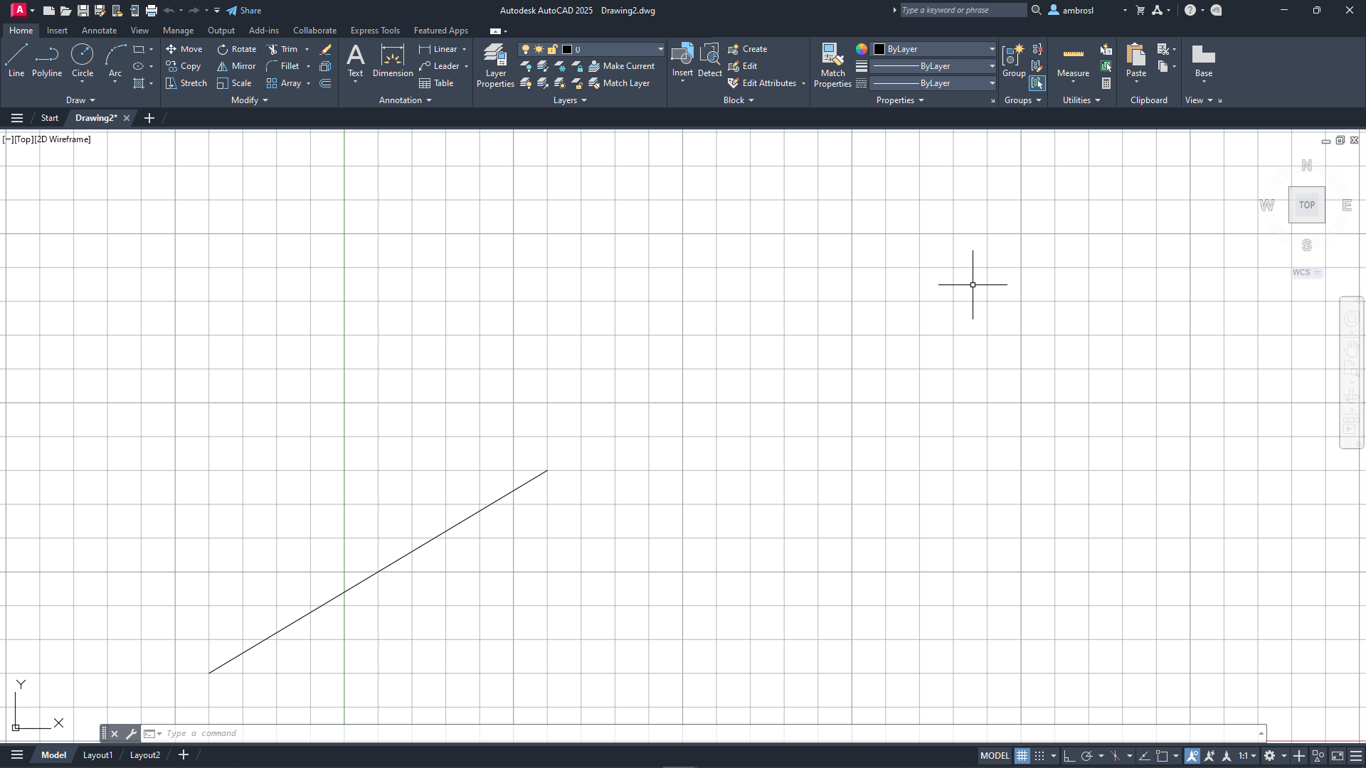
- On the Navigation Bar, located on the right side of the drawing area, click Zoom drop-down menu > Zoom All.Find
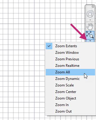
The line previously drawn should now be fully visible on-screen along with some space to work within based on the drawing's limits.
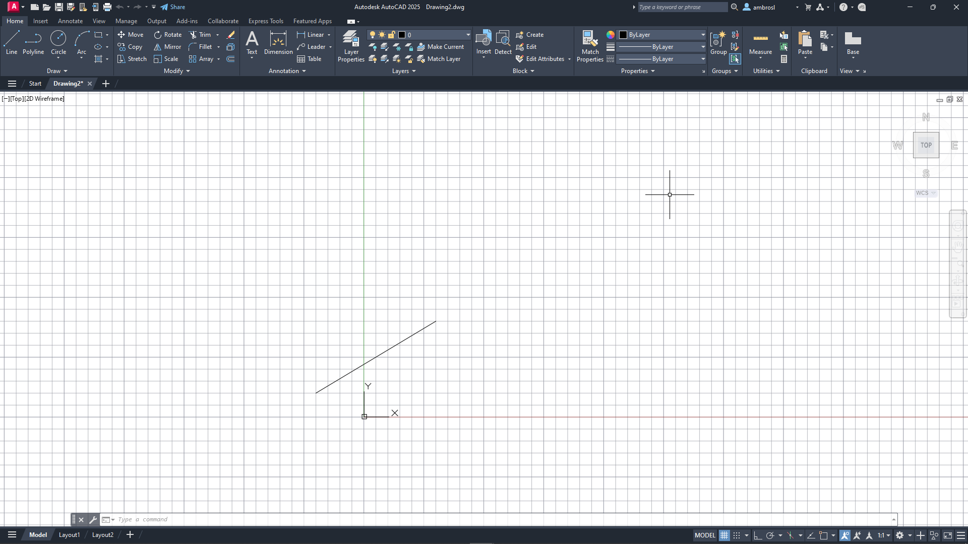
- On the Navigation Bar, click Zoom drop-down menu > Zoom Out.Find
The objects should now appear smaller and provide some additional space to work.
Absolute coordinates are entered differently if Dynamic Input is turned off. In that case, the # is not used to specify absolute coordinates. Dynamic Input can be toggled on or off by pressing the F12 key or
Draw with Relative Cartesian Coordinates
Use relative Cartesian coordinates when you know the location of a point in relation to the previous point. For example, to locate a point relative to the absolute coordinates (2,1), start the next coordinates with the @ symbol.
When prompted for a point, you can enter @ without a coordinate value to use the last specified point.
Try It: Create a Line Using Relative Cartesian Coordinates
Draw a line from an absolute coordinate point to a relative coordinate point.
Continue with the drawing created in the first exercise or create a new drawing: Try It: Create a Line Using Absolute Cartesian Coordinates.
- On the ribbon, click Home tab > Draw panel > Line.Find
At the Specify first point: prompt, enter #2,1.
At the Specify next point or [Undo]: prompt, enter @5,3.
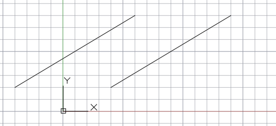
Entering @5,3 locates a point on the same X-axis as the second point in the previous example, resulting in two parallel lines. @ informs AutoCAD that the coordinate value is to be relative from the previous point. Here that means the coordinate should be located 5 units along the X-axis and 3 units on the Y-axis. The second coordinates final location is (7,4).
At the Specify next point or [Undo]: prompt, press Enter or the Spacebar to end the command.
Draw with Polar Coordinates
Polar coordinates allow you to locate a next point at a specific distance and direction relative to the previous point. For example, to locate a point relative from the previous point that is 5 units in length at an angle of 30 degrees, start the next coordinates with the @ symbol and separate the length and angle values with the < symbol.
Try It: Create a Line Using Polar Coordinates
Draw a line from an absolute coordinate point at a specified distance and angle using a polar coordinate.
Continue with the drawing created in the first exercise or create a new drawing: Try It: Create a Line Using Absolute Cartesian Coordinates.
- On the ribbon, click Home tab > Draw panel > Line.Find
At the Specify first point: prompt, enter #6,1.
At the Specify next point or [Undo]: prompt, enter @5<30.
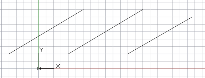
While the new line might look parallel to the previous lines, it is drawn at a true angle of 30-degrees and a length of 5 units.
At the Specify next point or [Undo]: prompt, press Enter or the Spacebar to end the command.
Use Direct Distance Entry
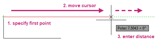
Entering coordinates only to draw objects can be time consuming and inefficient, especially when needing to calculate the distance between two coordinates to draw lines at specific lengths or to move objects a defined distance. Direct distance entry allows you to specify exact lengths and distances---by moving the cursor to indicate a direction and then entering the distance from the previous point. Using locking angles, Ortho mode, and polar tracking with direct distance entry helps you to draw lines at known angles with specific lengths efficiently.
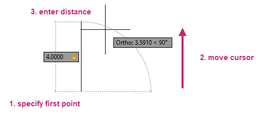
Try It: Use Direct Distance Entry
Draw a line that is 4 units long using direct distance entry.
Continue with the drawing created in the first exercise or create a new drawing: Try It: Create a Line Using Absolute Cartesian Coordinates.
- On the ribbon, click Home tab > Draw panel > Line.Find
At the Specify first point: prompt, specify any point in the drawing area by moving the cursor in the drawing area and clicking.
At the Specify next point or [Undo]: prompt, move the cursor away from the specified point and enter 4.
A line of 4 units in length is drawn from the first point in the direction of the cursor.
At the Specify next point or [Undo]: prompt, press Enter or the Spacebar to end the command.
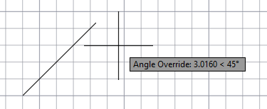
Lock Angular Cursor Movement
When creating or modifying objects, the coordinates you often specify will be in a known direction or angle from a previous point. There are several methods that can be used to restrict the direction in which coordinates are located: locking angles, Ortho mode, and polar tracking.
If you need to draw a line at a specified angle, you can lock the angle for the next point. For example, if the second point of a line needs to be located in a direction of 45-degrees from the previous point, you would enter <45 at the Command prompt.

After you move your cursor in the desired direction along the 45-degree angle, you can enter the distance of which the line segment is to be drawn.
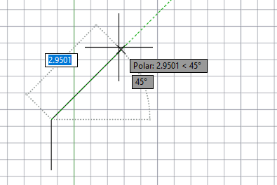
Try It: Create an Angular Line
Draw a line that is 3 units long at a 45 degree angle using using both locking angle and direct distance entry.
Continue with the drawing created in the first exercise or create a new drawing: Try It: Create a Line Using Absolute Cartesian Coordinates.
- On the ribbon, click Home tab > Draw panel > Line.Find
At the Specify first point: prompt, specify any point in the drawing area.
At the Specify next point or [Undo]: prompt, enter <45.
At the Specify next point or [Undo]: prompt, move the cursor along the locked 45-degree angle and enter 3.
A line of 3 units in length is drawn from the first point at a 45-degree angle.
At the Specify next point or [Undo]: prompt, press Enter or the Spacebar to end the command.
Ortho Mode
Coordinates are often specified in a horizontal or vertical direction (0 or 90 degrees) from a previous point, also known as orthogonal movement. Ortho mode is used to restrict cursor movement orthogonally, so it is parallel or perpendicular (90-degree increments) from the previous point.
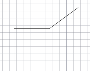
For example, after you specify the first point of a line, turn Ortho Mode on and move your cursor up, and then enter a distance at the Command prompt to draw a vertical line.
Try It: Create Orthogonal Lines
Draw several lines that are 2.5 units in length utilizing direct distance entry and ortho mode.
Continue with the drawing created in the first exercise or create a new drawing: Try It: Create a Line Using Absolute Cartesian Coordinates.
- On the status bar, click Restrict Cursor Orthogonally, if the button is not highlighted in blue.Find
- On the ribbon, click Home tab > Draw panel > Line.Find
At the Specify first point: prompt, specify any point in the drawing area.
At the Specify next point or [Undo]: drag the cursor up and enter 2.5.
Notice a line segment was drawn 2.5 units vertically.
At the Specify next point or [Undo]: prompt, drag the cursor to the right and enter 2.5.
A line segment of 2.5 units is drawn horizontally.
- On the status bar, click Restrict Cursor Orthogonally.Find
The button should no longer be highlighted in blue.
Tip:You can press the F8 key to toggle Ortho mode on or off, or you can hold the Shift key down to temporarily toggle Ortho mode on or off while specifying a point.
At the Specify next point or [Undo]: prompt, drag the cursor up and to the right, and then enter 2.5.
A diagonal line segment of 2.5 units should be drawn.
At the Specify next point or [Undo]: prompt, press Enter or the Spacebar to end the command.
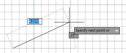
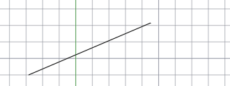
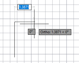
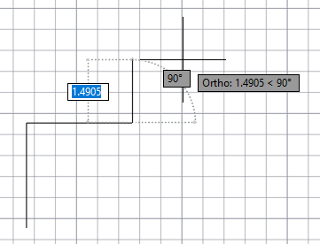
Polar Tracking
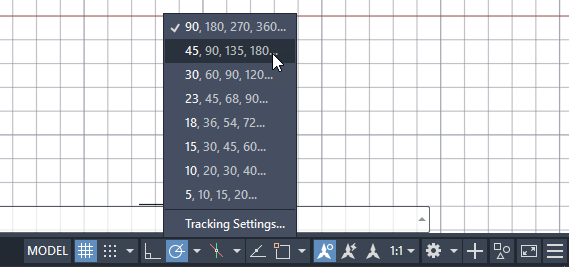
Like Ortho mode, polar tracking can also be used to restrict the movement of the cursor in the horizontal and vertical directions (0 or 90 degrees) from the previous point. In addition to restricting cursor movement in the horizontal and vertical directions, the angle increments of polar tracking can be adjusted. Angle increments can be set to as small as every 5-degrees to every 90-degrees. A green extension line appears in the drawing area indicating the restricted angle of movement.
For example, after you specify the first point of the line below and move your cursor to the right, the polar tracking extension line appears. With the cursor movement restricted, enter a distance at the Command prompt to specify a precise horizontal length for the line.
By default, polar tracking is turned on and restricts your cursor to a horizontal or vertical direction (0 or 90 degrees).
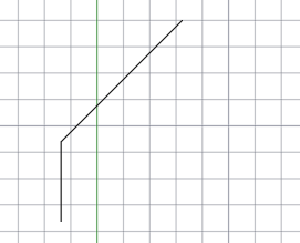
Try It: Create Angular Lines with Polar Tracking
Draw several lines of different lengths utilizing direct distance entry and polar tracking.
Continue with the drawing created in the first exercise or create a new drawing: Try It: Create a Line Using Absolute Cartesian Coordinates.
- On the status bar, click Restrict Cursor to Specified Angles, if the button is not highlighted in blue.Find
On the status bar, right-click over Restrict Cursor to Specified Angles and choose 45.
- On the ribbon, click Home tab > Draw panel > Line.Find
At the Specify first point: prompt, specify any point in the drawing area.
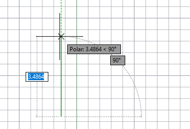
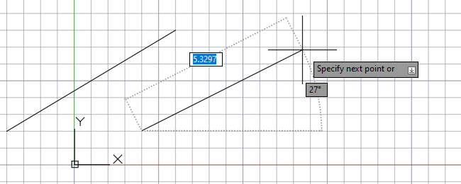
At the Specify next point or [Undo]: prompt, drag the cursor up at an angle of 90-degrees from the first point and enter 1.5.
When you move the cursor up at an angle of 90-degrees, you should notice a green extension line indicating the polar angle that will be used to draw the line segment. A line segment should be drawn vertically with a length of 1.5 units.
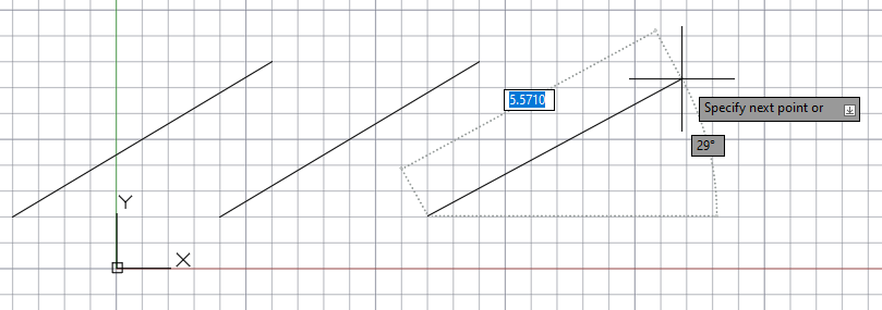
At the Specify next point or [Undo]: prompt, drag the cursor to the right at an angle of 45-degrees from the previous point and enter 3.25.
A line segment of 3.25 units is drawn at 45-degrees.
At the Specify next point or [Undo]: prompt, press Enter or the Spacebar to end the command.
- On the status bar, right-click over Restrict Cursor to Specified Angles and choose 90.Find
Snap to Precise Points on Objects
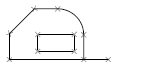
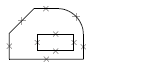
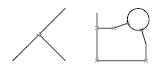
Objects that make up your designs rarely fall on precise coordinates. By far, the most important way to specify precise locations on objects is to use object snaps. In the following illustration, several different kinds of object snaps are represented by markers.
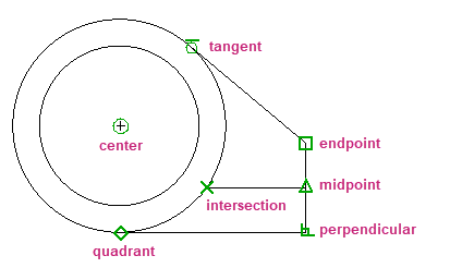
Object snaps become available during a command whenever you are prompted to specify a point. For example, as you draw a new line and move the cursor near the endpoint of an existing line, the cursor will automatically snap to it and is identified with a AutoSnap marker and tooltip.
AutoSnap Marks of Common Object Snaps
The following table illustrates commonly used object snaps.
| Object Snap | Example | Snaps To |
|---|---|---|
Endpoint |
 |
Object endpoints |
Midpoint |
 |
Object midpoints |
Intersection |
 |
Object intersections or, for single object snaps, locations where intersections would occur if objects were extended |
Center |
 |
Center points of circles, arcs, or ellipses |
Quadrant |
 |
Quadrants of circles, arcs, or ellipses |
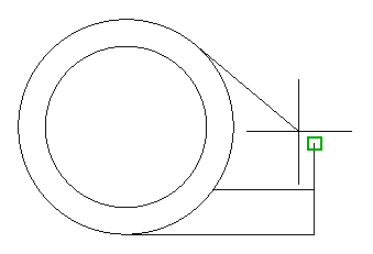
Perpendicular |
 |
Points on objects that form a perpendicular alignment with the last point specified |
Tangent |
 |
Points on a circle or arc that, when connected to the last point, forms a line tangent to the object |
Use Single Object Snaps
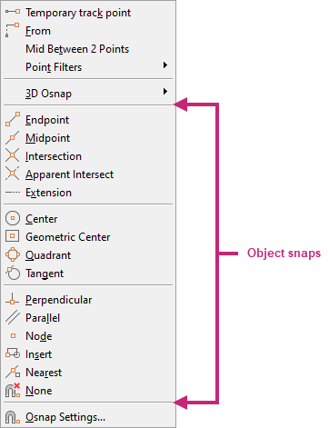
When prompted to specify a point, you can specify a single object snap by holding down Shift, right-clicking, and choosing an object snap from the menu.
Once you have specified an object snap, use the cursor to specify a point on an object.
Set Running Object Snaps
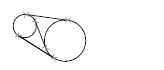
Often, you will be using the same object snaps repeatedly as you create and modify objects. An object snap can be set active, known as a "running" object snap, until you turn it off. For example, you might set Center as a running object snap if you need to dimension between the centers of two circles or draw a connecting line between a series of circles.
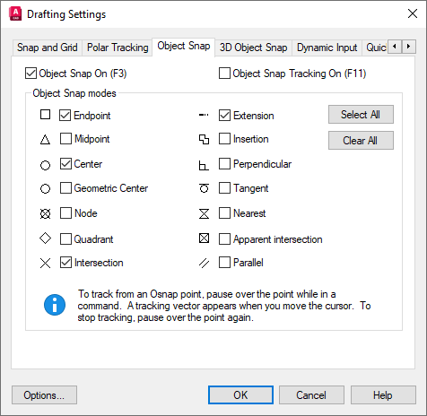
When running object snaps are turned on, multiple running object snaps can be active at a time, such as Endpoint, Center, and Intersection. The default active running object snaps can be set using the Drafting Settings dialog box.
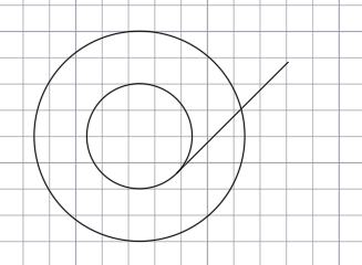
Try It: Use Object Snaps
Use running and temporary object snaps to precisely position circles and lines in a drawing based on existing geometry points.
Continue with the drawing created in the first exercise or create a new drawing: Try It: Create a Line Using Absolute Cartesian Coordinates.
- On the status bar, click Snap Cursor to 2D Reference Points, if the button is highlighted in blue.Find
The button should no longer be highlighted, indicating running object snaps are turned off.
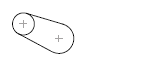
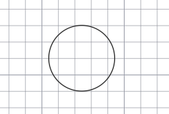
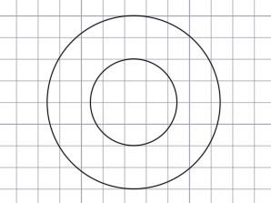
- On the ribbon, click Home tab > Draw panel > Circle drop-down menu > Center, Radius.Find
At the Specify center point for circle or [3P/2P/Ttr (tan tan radius)]: prompt, specify any point in the drawing area.
At the Specify radius of circle or [Diameter]: prompt, enter 1.
Press Enter to repeat the CIRCLE command and draw a second circle.
At the Specify center point for circle or [3P/2P/Ttr (tan tan radius)]: prompt, hold down the Shift key and right-click.
- From the Object Snaps menu, choose Center.
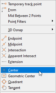
At the Specify center point for circle or [3P/2P/Ttr (tan tan radius)]: _cen of prompt, move the cursor to the edge of the circle and click when you see the Center AutoSnap marker.
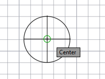
At the Specify radius of circle or [Diameter] <1.0000>: prompt, enter 2.
- On the status bar, click Snap Cursor to 2D Reference Points.Find
The button should now be highlighted, indicating running object snaps are turned on.
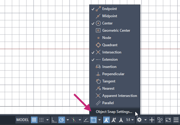
On the status bar, right-click over Snap Cursor to 2D Reference Points and choose Object Snap Settings.
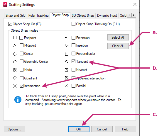
In the Drafting Settings dialog box, Object Snaps tab, do the following:
Click Clear All.
Click Intersection and Tangent.
Click OK to save the changes and exit the dialog box.
- On the ribbon, click Home tab > Draw panel > Line.Find
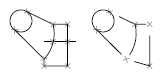
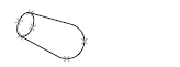
At the Specify first point: prompt, move the cursor to the edge of the inner circle and click when you see the Deferred Tangent AutoSnap marker.
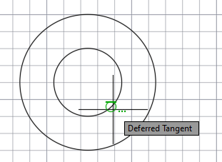
At the Specify next point or [Undo]: prompt, enter @3<45.
At the Specify next point or [Undo]: prompt, press Enter to end the command.
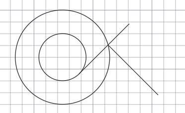
Press Enter to repeat the LINE command and draw a second line.
At the Specify first point: prompt, move the cursor to the intersection of the line and outer circle, and then click when you see the Intersection AutoSnap marker.
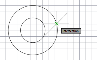
At the Specify next point or [Undo]: prompt, enter @3<315.
At the Specify next point or [Undo]: prompt, press Enter to end the command.
- From the Application Menu, click Close > Current Drawing.Find
You can also click the Close button in the upper-right corner of the drawing area.
In the AutoCAD message box, click No to discard the changes to the current drawing.
To cycle through all points that match the single or running object snaps set on a particular object, press Tab.
Summary
You learned about a range of techniques and features that help to ensure designs are completed with precision and accuracy. Cartesian and polar coordinates were used to draw objects, and then you learned to draw objects faster using direct distance entry, Ortho mode and polar tracking. Additionally, you learned to snap to precise points on objects using single and running object snaps.