
8. Change Object Properties and Organize Objects with Layers (AutoCAD Foundations)
Most graphical objects of a drawing share several general properties which control their appearance. These general properties include color, linetype, linetype scale, lineweight, transparency, and plot style among others. Properties such as color and linetype can be changed per individual object, or across many objects with the use of layers.
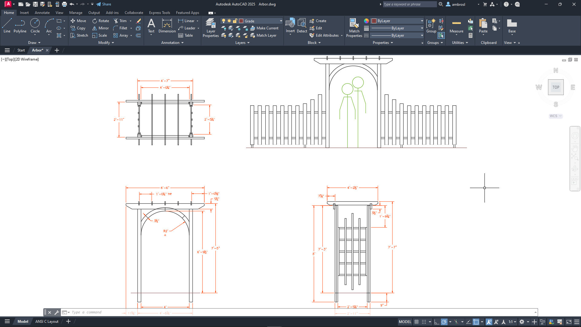
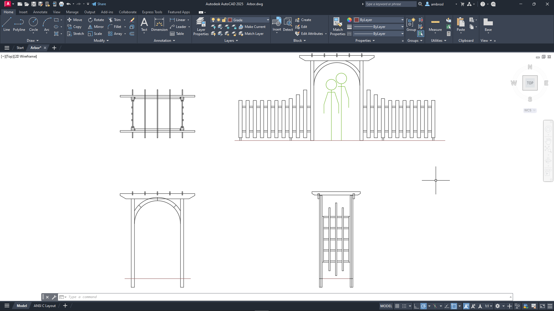
In the following design, the walls, exterior stone facing, doors, fixtures, cabinetry, HVAC, electrical, and text were assigned layers with different colors and linetypes to help differentiate between them. When a drawing becomes visually complex, you can hide the objects that you currently do not need to see with the use of layers. In the illustration below, on the right, the objects that represent doors and electrical wiring were temporarily hidden by turning off their assigned layers.
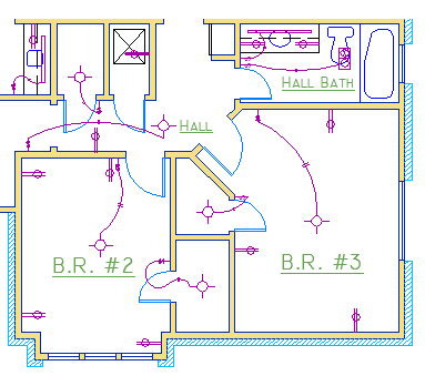
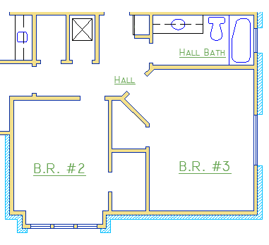
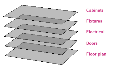
You gain this level of control by organizing the objects in your design on layers that are associated with a specific function or purpose. It might be helpful to think of layers as clear plastic sheets stacked on top of each other.
With layers, you can
Associate objects by their function or location
Display or hide all related objects in a single operation
Enforce color, linetype, and other property standards for each layer
Resist the temptation to create everything on one layer and to control the appearance of individual objects by changing their general properties. Layers are the most important organizing feature available for your drawings.
The following video demonstrates some of the learning objectives covered in this topic:
Learning Objectives
Prerequisites
You should know how to do the following before continuing:
- Create, open, save, and view drawings
- Work with commands
- Create basic 2D objects (lines and circles)
- Select, modify, and duplicate objects
Prepare for the Exercises
To follow along with the exercises in this topic, download the ZIP file containing the sample drawings.
![]() Download: Sample drawing files used for the following exercises
Download: Sample drawing files used for the following exercises
The ZIP file contains all drawings used for the exercises and only needs to be downloaded once. Keep the ZIP file to restore the original state of the sample drawings.
Change the Properties of Objects
All objects that you create have properties. Object properties control the appearance and geometric characteristics of an object. The general properties that are common to all objects are listed below. All other properties are specific to that type of object.
|
|
When objects are selected, you can use the Properties palette to verify and change property settings. If you select an object in your drawing, here is what you might see in the Properties palette.
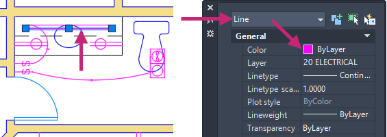
Notice that the current properties for the selected object are displayed in the Properties palette. You can change any of these properties by clicking it and changing the value. A property that is set to "ByLayer" inherits its value from its assigned layer. In the previous example, the line object's color of purple is inherited from its assigned layer of 20 ELECTRICAL.
If you select several objects, only their common properties are listed in the Properties palette. If you change one of these properties, all selected objects are changed in one operation.
To clear the current object selection, press Esc.
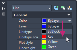
When the Properties palette is displayed and no objects are selected, the current property values are of those to be assigned to newly created objects. Property values listed as ByLayer, indicate properties that inherit their values from the layer to which the object is assigned. For example, changing the Color property value from ByLayer to Red causes all subsequent objects to be assigned the Red color which overrides the value of the assigned layer.
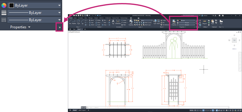
The Properties palette takes up a lot of space. For quick access to the most common properties, you can use the Properties panel on the ribbon. As you can see in this example, the listed properties will all be determined by the current layer.
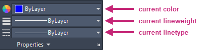
The Properties panel works similar to the General section of the Properties palette. When you select an object, the current property values are shown instead of the properties that will be assigned to a newly created object. With the Properties panel, you can easily change the General properties of one of more selected objects.
Try It: Verify and Change Object Properties
Verify and change the Color property value of an object using the Properties palette and Properties panel on the ribbon.
- On the Quick Access toolbar, click Open.Find
In the Select File dialog box, browse to the sample files you previously downloaded and select the arbor.dwg file. Click Open.
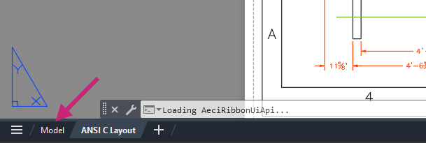
On the layout tabs, below the drawing window, click the Model tab.
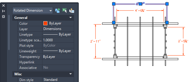
Press Esc to make sure no objects are selected and then select a dimension object in the drawing.
- On the ribbon, click Home tab > Properties panel > Dialog box launcher.Find
To work with a palette. The following is a quick introduction to working with a palette:
If a palette is collapsed or set to auto-hide, moving the cursor over its title bar gives the palette focus and expands it.
Clicking the Auto-hide button keeps the palette expanded or allows it to collapse when it doesn't have focus.
Clicking and dragging over its title bar allows you to reposition the palette on screen.
Positioning the cursor allow the top, bottom, or opposite edge from the title bar allows you to resize the palette.
Clicking the Close button hides or dismisses the palette.
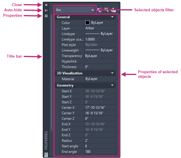
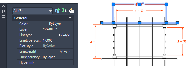
On the Properties palette, look at the property values under the General section.
The layer of the selected dimension object is named Dimensions and its color is Reddish. The color, linetype, and lineweight properties of the object are set to ByLayer which indicates the object is inheriting those property values from its assigned layer.
 Note:
Note:The current values of several properties for the selected object are also displayed on the Properties panel of the ribbon.
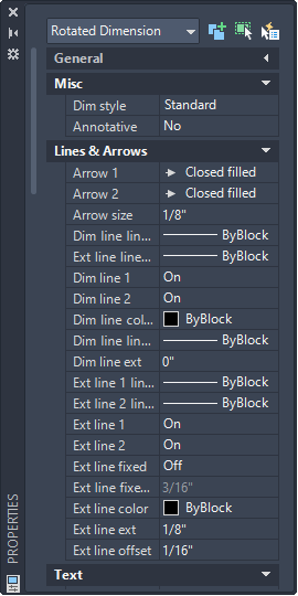
Examine the other properties of the dimension object displayed on the Properties palette.
Select several more objects of different types and colors in the drawing.
Notice that only the properties that are common to all selected objects are listed. The Layer property value likely shows as *VARIES*. This is because the selected objects are on more than one layer.
Press Esc to deselect all selected objects.
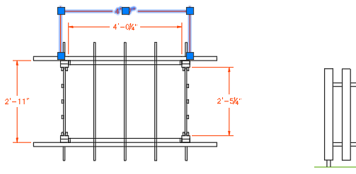
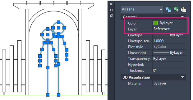
Select all the objects that make up the silhouettes under the arch trellis.
These objects are assigned the Reference layer and have a color value of ByLayer.
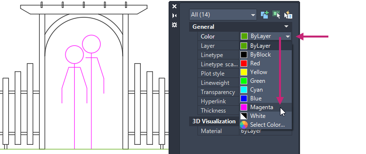
On the Properties palette, click the Color property and choose Magenta from the drop-down list.
These objects now have the color override of Magenta and no longer inherit their color from the Reference layer.
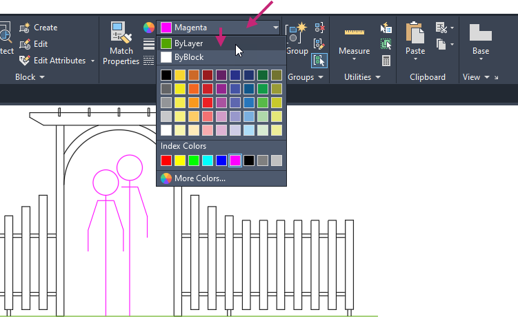
- On the ribbon, click Home tab > Properties panel > Color drop-down list and choose ByLayer.Find
The objects once again inherit their color from the Reference layer.
Press Esc to deselect all selected objects.
- On the Quick Access toolbar, click Save.Find
Don't close the drawing, as you will continue to use it in the next exercise.
For more information, see Have You Tried: Matching Properties.
Create and Assign Layers
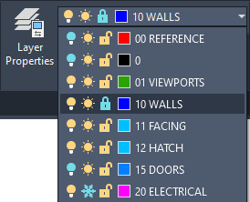
Layers are used to help control the appearance and visibility of objects along with the ability to lock objects so they can't be selected and accidentally modified. You manage layers in a drawing with the Layer Properties Manager. The Layer Properties Manager is a palette that can be used to create and modify layers. Here's what you might see in the Layer Properties Manager for a drawing that represents a floor plan.
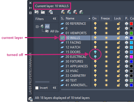
As you can see in the illustration, layer 10 WALLS is the current layer. All new objects are automatically assigned this layer. In the list of layers, the green check next to layer 10 WALLS confirms that it is the current layer.
In the column labeled On, notice that the light bulb icons for two layers are a different color; light blue. These layers were turned off to hide the doors and electrical wiring in the floor plan.
Notice that each layer name starts with a two-digit number. This convention makes it easy to control the order of the layers because their order does not depend on the alphabet.
For complex drawings, you might want to consider a more elaborate layer naming standard. For example, layer names could begin with 3 digits followed by a naming code that accommodates multiple floors in a building, project numbers, sets of survey and property data, and so on. There are also industry standards for layer names you might want to use, such as AIA and ISO.
Best Practices
Layer 0 is the default layer that exists in all drawings and has some esoteric properties which can affect objects in blocks. Instead of using this layer, it's best to create your own layers with meaningful names.
Any drawing that contains at least one dimension object automatically includes a reserved layer named Defpoints. Objects assigned the Defpoints layer are not plotted, and it is recommended to not place objects you create on this layer.
Create a layer for behind-the-scenes construction geometry, reference geometry, and notes that you usually do not need to see or plot or print.
Create a layer for layout viewports.
Create a layer for all hatches and fills. This lets you turn them all on or off in one action.
Try It: Create and Set a Layer Current
Create a new layer and then set it current with the Layer Properties Manager palette and Layers panel on the ribbon.
If you closed or haven't opened the arbor.dwg sample file yet, open it now.
- On the Quick Access toolbar, click Open.Find
In the Select File dialog box, browse to the sample files you previously downloaded and select the arbor.dwg file. Click Open.
If the Model tab is not current, on the layout tabs below the drawing window, click the Model tab.
- On the ribbon, click Home tab > Layers panel > Layer Properties.Find

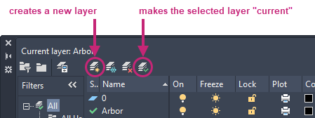
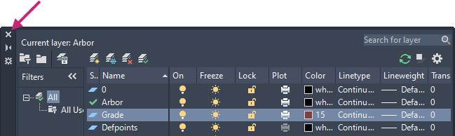
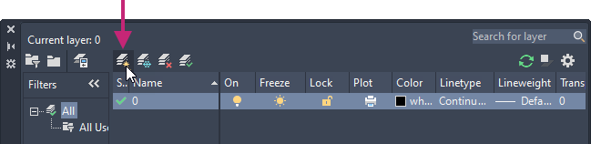
On the Layer Properties Manager, click New Layer.
In the in-place editor, enter Grade.
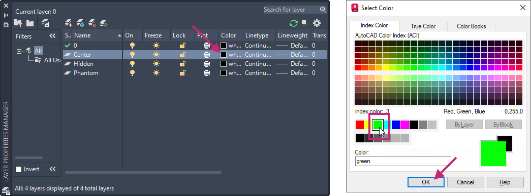
On the Grade layer row, Color column, click the color swatch.
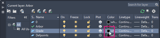
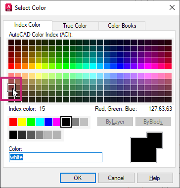
In the Color dialog box, Index Color tab, select the ACI 15 color swatch or type 15 in the Color text box. Click OK.
On the Layer Properties Manager, click the Close button on the palette's title bar to close the palette.
After the layers you need have been created, you commonly don't need to keep the Layer Properties Manager open.
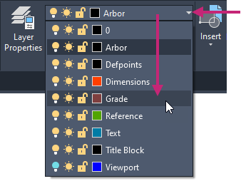
On the ribbon, click Home tab > Layers panel > Layers drop-down list and select Grade.
The Grade layer is now set current.
 Note:
Note:You can also set a layer current on the Layer Properties Manager. Select a layer and click Set Current to set the layer current, or double-click the name of the layer in the Name column.
Select the horizontal line below each view of the arbor trellis, there are a total of three lines.
Notice on the ribbon, the Layers drop-down list reflects the layer assigned to the selected lines is Reference.
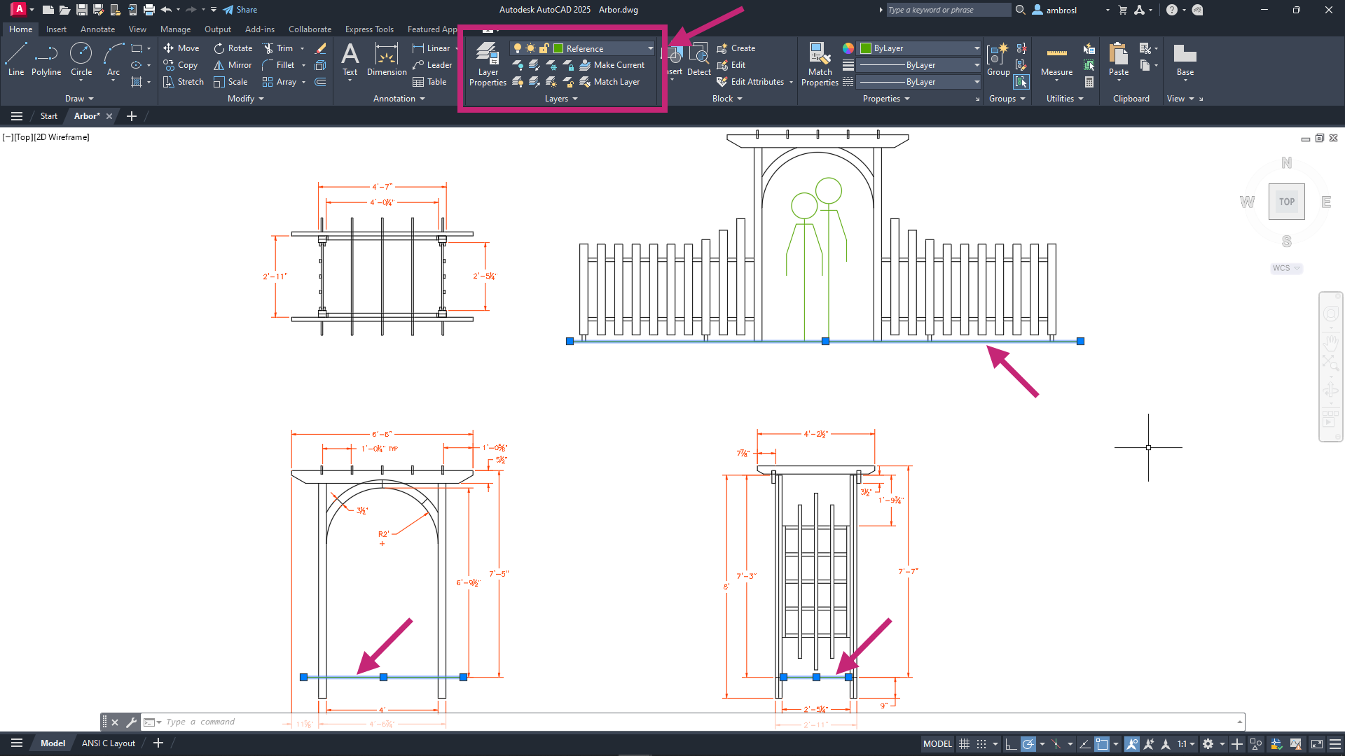
On the ribbon, click Home tab > Layers panel > Layers drop-down list and select Grade.
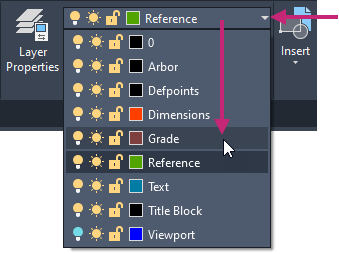
The Grade layer is now assigned to the three selected lines.
Press Esc to deselect all selected objects.
- On the Quick Access toolbar, click Save.Find
Don't close the drawing, as you will continue to use it in the next exercise.
Control the Visibility of Objects with Layers
Layers help control the appearance of objects. Additionally, layers also control the visibility and state of objects. All objects on a layer can be locked to avoid being modified. The visibility of objects can also be controlled with layers to reduce the complexity of objects on-screen and when plotted/printed. The visibility of objects is controlled by two different states: On/Off and Thawed/Frozen. Freezing objects can help improve performance in very large drawings.
You can change the visibility or state of a layer with the icons on the Layer Properties Manager palette or the Layers drop-down list on the Layers panel of the ribbon.
Turn off layers. Reduces the visual complexity of your drawing while you work, but objects on the layers remain selectable when using the All object selection mention.

Freeze layers. Turns off layers and keeps the objects from being selected. Freezing layers can improve performance in very large drawings.

Lock layers. Prevents accidental changes to the objects on these layers. Also, the objects on locked layers appear faded, which helps reduce the visual complexity of a drawing but still lets you see the objects faintly.

Try It: Change the Visibility of and Lock Objects
Change the visibility of and lock the state of layers to control the objects placed on those layers.
If you closed or haven't opened the arbor.dwg sample file yet, open it now.
- On the Quick Access toolbar, click Open.Find
In the Select File dialog box, browse to the sample files you previously downloaded and select the arbor.dwg file. Click Open.
If the Model tab is not current, on the layout tabs below the drawing window, click the Model tab.
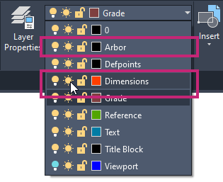
On the ribbon, click Home tab > Layers panel > Layers drop-down list.
From the Layers drop-down list, click the Sun icon adjacent to the Dimensions layer.
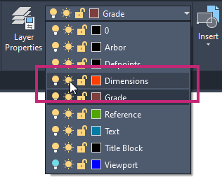
The icon is now shown as a Snowflake and the objects on the Dimensions layer are frozen and hidden. Freezing layers with objects on them that you current don't need can help to reduce visual clutter on-screen.
From the Layers drop-down list, click the Unlocked Padlock icon adjacent to the Arbor layer.
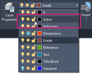
The objects on the Arbor layer are now locked and cannot be selected. You will also notice the objects on the Arbor layer are faded to make them less prominent.
- On the ribbon, click Home tab > Modify panel > Erase.Find
At the Select objects: prompt, use a window selection to select the silhouettes, arch trellis, and grade objects.
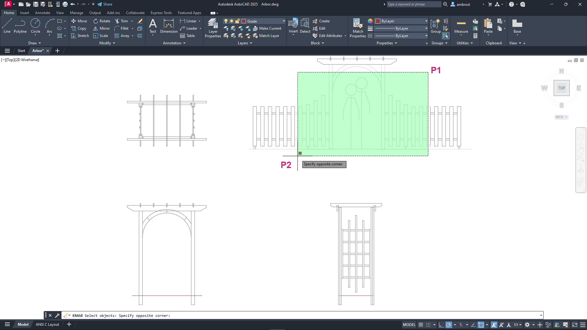
Press Enter to erase the selected objects.
You should notice only the silhouettes and grade objects are erased since the arch trellis is placed on the Arbor layer which is locked.
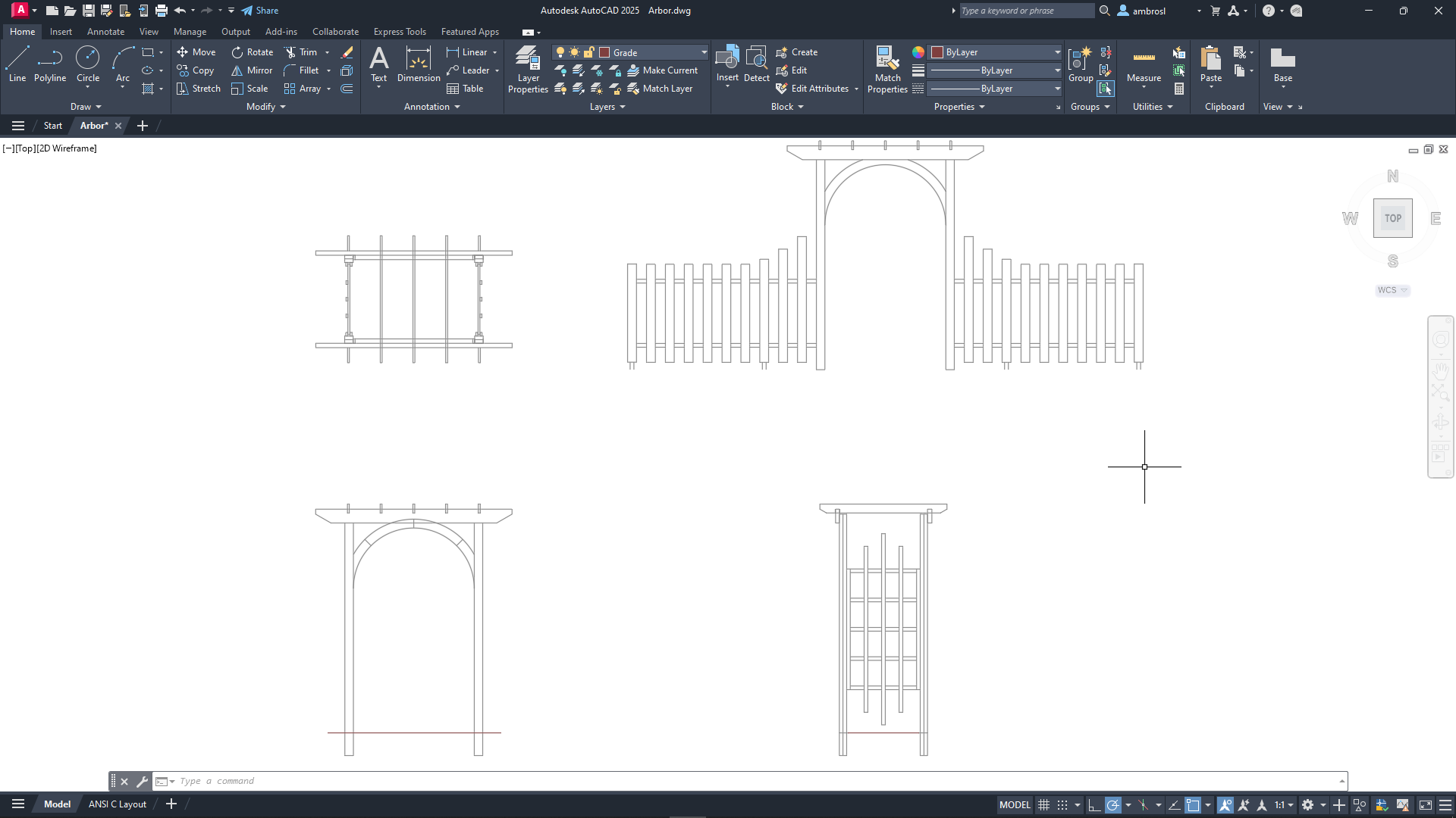
- On the Quick Access toolbar, click Undo.Find
The erasing of the objects is reversed and they are restored.
On the ribbon, click Home tab > Layers panel > Layers drop-down list.
From the Layers drop-down list, unlock the Arbor layer and thaw the Dimensions layer by clicking the Locked Padlock and Snowflake icons.
- On the Quick Access toolbar, click Save.Find
Don't close the drawing, as you will continue to use it in a later exercise.
Load, Assign, and Scale Linetypes
Linetypes are used to communicate parts of a design that are not visible from the current viewpoint or are there only to help communicate measurements. The Continuous linetype is available by default, but non-continuous linetypes that contain dashes, gaps, dots, and even text are also available. Linetypes other than Continuous are stored in Linetype (LIN) files and made available for use by loading them into a drawing file. If you commonly use specific linetypes, they can be added to the drawing template you use when creating a new drawing.
You can associate a single linetype with all objects on the same layer, or you can assign linetypes individually to objects.
Scale Linetypes
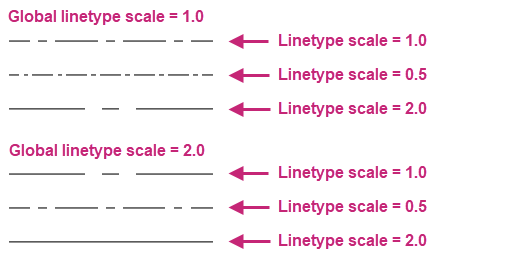
When you scale views in layout viewports, you can create inconsistencies in the appearance of linetypes. In non-continuous linetypes, the length of dashes and gaps between them and dots may increase or decrease. You can set the scaling to correspond to the model or layout scale or to remain the same at any zoom scale.
Linetype scaling is controlled by:
Global Scale Factor. Sets the global scale factor for all linetypes.
Current Object Scale. Sets the linetype scale for newly created objects as a percentage of the global scale factor.
Use Paper Space Units for Scaling. Scales the linetypes in paper space and model space identically.
Try It: Load Linetypes
Load linetypes for use in a drawing from a Linetype (LIN) file.
- On the Quick Access toolbar, click New.Find
In the Select Template dialog box, select the acad.dwt drawing template file. Click Open.
A new drawing is created based on the acad.dwt drawing template.
- On the status bar, click Drawing Display Grid, if the button is highlighted in blue.Find
The grid displayed in the background is removed, making it easier to see the linetypes applied to the objects and changes to the linetype scales during the next several exercises.
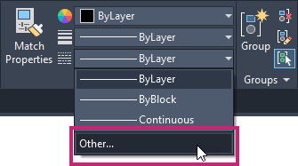
- On the ribbon, click Home tab > Properties panel > Linetypes drop-down list > Other.Find
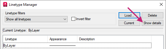
In the Linetype Manager dialog box, click Load.
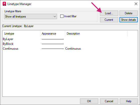
In the Load or Reload Linetypes dialog box, hold down the Ctrl key and select CENTER, HIDDEN, and PHANTOM from the Available Linetypes list. Click OK.
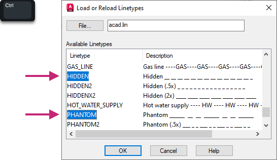
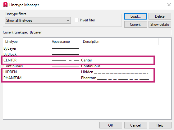
The Center, Hidden and Phantom linetypes are now available to be assigned to individual objects and layers.
Click OK.
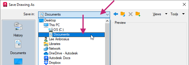
- On the Quick Access toolbar, click Save.Find
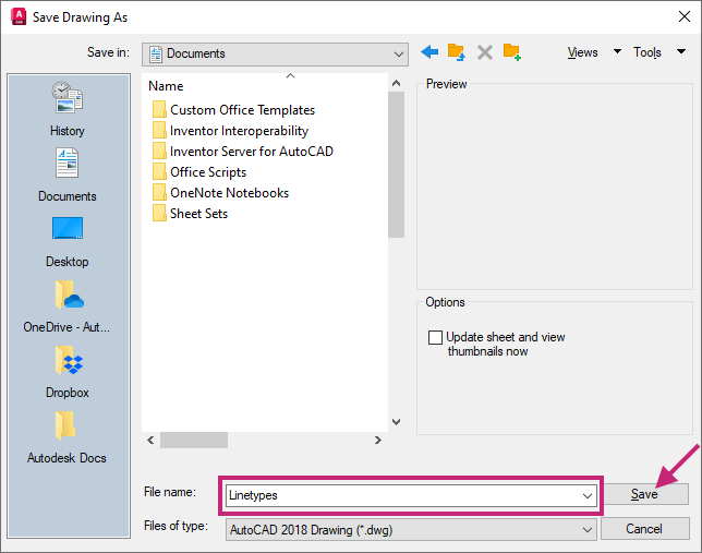
In the Save Drawing As dialog box, browse to the Documents folder.
In the File Name text box, select the current name and type Linetypes. Click Save.
Don't close the drawing, as you will continue to use it in the next exercise.
Try It: Assign Linetypes to Individual Objects
Assign loaded linetypes to objects in a drawing.
Continue with the Linetypes.dwg file created in the previous exercise: Try It: Load Linetypes.
If you didn't complete the previous exercise, do so now.
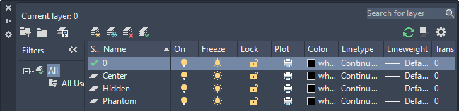
Create three new layers named:
- Center
- Hidden
- Phantom
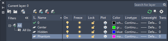
Once the layers have been created, assign the layers the following colors:
- Center - Color: Green (3)
- Hidden - Color: Blue (5)
- Phantom - Color: Magenta (6)
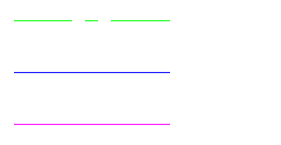
In the drawing area, draw three parallel horizontal lines that are 3 units in length and about 1 unit apart.
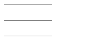
Zoom to the extents of the drawing and then zoom out to to ensure you can see how the linetypes appear as they are assigned to each line.
Assign one line to each layer of the layers you created in Step 2.
You can assign the layer to the objects with the Properties palette or Layers drop-down list on the Properties panel of the ribbon. Select one of the lines and then assign the layer, make sure to deselect the selected line before selecting the next line.
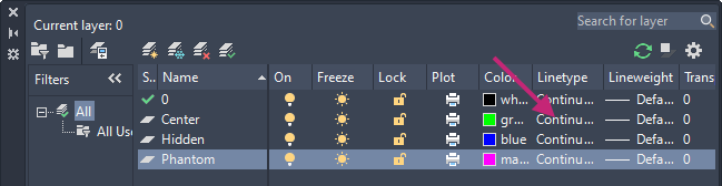
On the Layer Properties Manager, Center layer row, click in the Linetype column.
If the Linetype column is hard to see, move the cursor to the edge of the Layer Properties Manager opposite the title bar and drag to resize the palette.
In the Select Linetype dialog box, select CENTER and click OK.
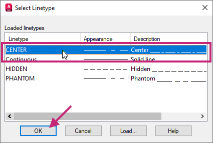
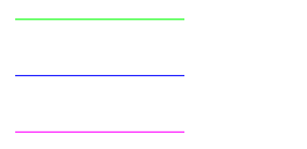
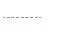
Notice the line assigned the Center layer inherits the CENTER linetype.
Assign the HIDDEN linetype to the Hidden layer, and then assign the PHANTOM linetype to the Phantom layer.
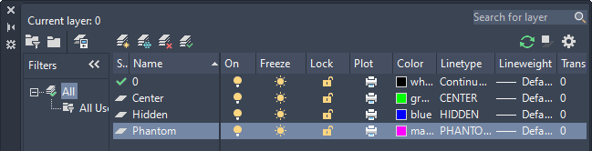
Notice the linetype assigned to each of the layers is inherited by each of the lines.
- On the Quick Access toolbar, click Save.Find
Don't close the drawing, as you will continue to use it in the next exercise.
Try It: Scale Linetypes
Adjust the global scale for linetypes along with individually for objects.
Continue with the Linetypes.dwg file created earlier and modified in the previous exercises: Try It: Load Linetypes and Try It: Assign Linetypes to Individual Objects.
If you didn't complete the previous two exercises, do so now.
Copy the three lines twice, placing them side-by-side and to the right of the original created lines.
Zoom to the extents of the drawing and then zoom in on the three sets of lines to see the impact of changing linetype scales.
- On the ribbon, click Home tab > Properties panel > Linetypes drop-down list > Other.Find
In the Linetype Manager dialog box, under Details and in the Global Scale Factor text box, change the value to 2.
If the Details section is not visible, click Show Details.
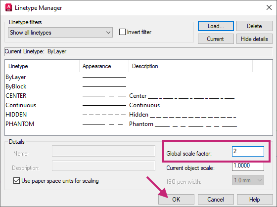
Click OK.
Notice that the dashes and gaps of the linetypes assigned to all objects are scaled up globally.

At the Command prompt, enter ltscale.
At the Enter new linetype scale factor <2.0000>: prompt, enter 1.
The previous global scale applied to all linetypes is restored.
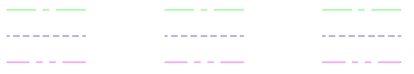
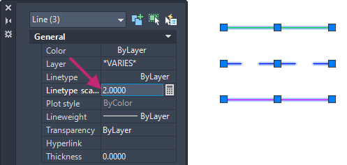
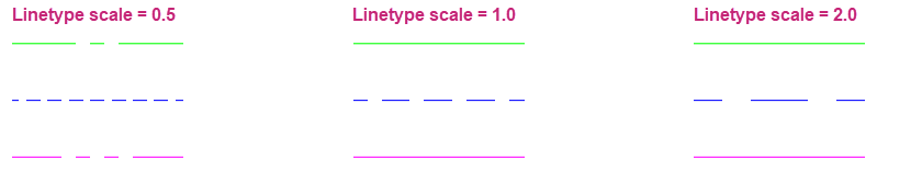
Select the original three lines you created, those on the left.
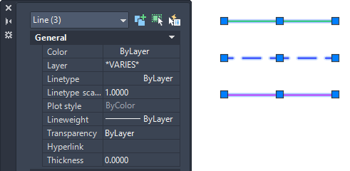
Display the Properties palette, if not currently displayed.
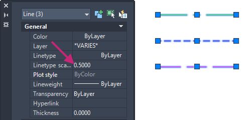
On the Properties palette, click the Linetype Scale property and change the value to 0.5.
You should see the linetypes are scaled down by 1/2 or 50% of the global scale factor.
Press Esc to make sure no objects are selected.
Select the right-most set of three lines, one of the sets you had created by copying the original objects.
On the Properties palette, click the Linetype Scale property and change the value to 2. Press Esc to deselect all selected objects.
You should see the linetypes are scaled up by 2 times or 200% of the global scale factor.
- On the Quick Access toolbar, click Save.Find
Optionally, close the drawing as you will use a different sample drawing in the next exercises.
Assign a Lineweight
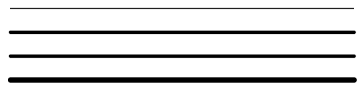
Lineweights provide a way to control the line thicknesses of objects. Thick and thin lines can be used to show cuts in sections, depth in elevations, dimension lines and tick marks, and differences in details. Lineweights are independent of the current view scale and regardless of how the lineweights appear on screen, objects always plot or print at the lineweight specified.
Like color and linetypes, lineweights can be applied individually or inherited from the layer assigned to objects.
It's usually best to leave lineweights turned off while you work. Lineweights can obscure nearby objects when you use object snaps. You might want to turn them on for checking purposes just before you plot or print.
Try It: Display and Assign Lineweights
Assign lineweights to objects in a drawing.
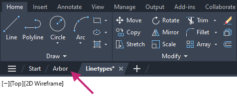
Switch to the arbor.dwg sample file by clicking the Arbor drawing file tab.
If you closed or haven't opened the arbor.dwg sample file yet, open it now.
- On the Quick Access toolbar, click Open.Find
In the Select File dialog box, browse to the sample files you previously downloaded and select the arbor.dwg file. Click Open.
If the Model tab is not current, on the layout tabs below the drawing window, click the Model tab.
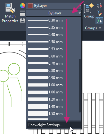
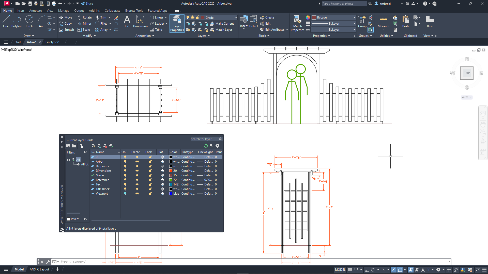
- On the ribbon, click Home tab > Properties panel > Lineweights drop-down list > Lineweight Settings.Find
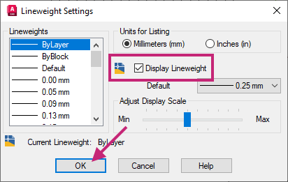
In the Lineweight Settings dialog box, check the Display Lineweight option and then click OK.
- Click Home tab > Layers panel > Layer Properties.Find
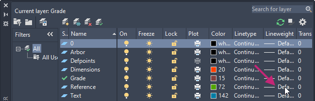
On the Layer Properties Manager, click in the Lineweight column of the Reference layer.
 Note:
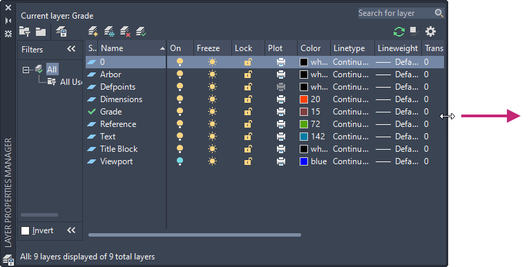
Note:If the Lineweight column is hard to see, move the cursor to the edge of the Layer Properties Manager opposite the title bar and drag to resize the palette.
In the Lineweight dialog box, select 0.30 mm and then click OK.
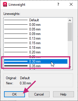
The lines of the objects on the Reference layer are thickened.
- On the status bar, click the Show/Hide Lineweight button to turn off the display of lineweights.Find
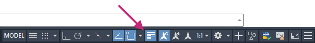 If the Show/Hide Lineweight button is not shown on the status bar, click the Customization button (far right) and choose LineWeight.Find
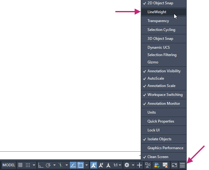 Remember:
The Show/Hide Lineweight setting can also be found in the Lineweight Settings dialog box.
- On the Quick Access toolbar, click Save.Find
Optionally, close the drawing since this is the final exercise.
Summary
You learned how to control the appearance of objects by changing individual property values of objects and the importance of layers to organize objects in a drawing. Additionally, you also learned that objects can inherit property values of the layer to which they are assigned, and the visibility and lock status of objects can be controlled by the layer.
Related Commands
| Command | Description |
|---|---|
| COLOR | Sets the color for new objects. |
| LAYER | Manages layers and layer properties. |
| LINETYPE | Loads, sets, and modifies linetypes. |
| LTSCALE | Sets the global linetype scale factor. |
| LWEIGHT | Sets the current lineweight, lineweight display options, and lineweight units. |
| MATCHPROP | Applies the properties of a selected object to other objects. |
| PROPERTIES | Controls properties of existing objects. |