
To specify 1-line
To specify 2-line
To specify single-line graphics
- In the Piping workspace, click
 .
.
- In the left pane of Style Manager, expand Piping Objects.
- Expand Pipe System Definitions.
- Select a system.
- In the right pane, click the Single Line Graphics tab.
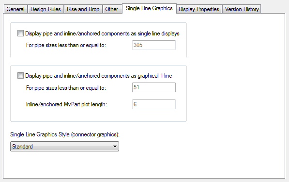
- Choose an action below:
If you want to… then… display pipe and equipment as scaled 1-line select Show pipe and inline/anchored components as Single Line displays. Then for pipe sizes less than or equal to, enter an upper limit diameter.
display pipe and equipment as graphical 1-line, not to scale, with equipment represented by schematic symbols select Display pipe and inline/anchored components as graphical 1-line. For pipe sizes less than or equal to, enter an upper limit diameter. Then for Inline/anchored MvPart plot length, enter a plot length.
- On the Single Line Graphics tab, clear Display pipe and inline/anchored components as single line displays and Display pipe and inline/anchored components as graphical 1-line.
- On the Single Line Graphics tab, select Display pipe and inline/anchored components as single line displays.
- For pipe sizes less than or equal to, enter an upper limit diameter.
- Select Display pipe and inline/anchored components as graphical 1-line.
- For pipe sizes less than or equal to, enter an upper limit diameter.
- Enter a plot length for inline/anchored MvParts.
- For Single Line Graphics Style (connector graphics), select a style. Tip: The blocks specified in the selected style will appear in the 1-line displays for the current system.