
Use this procedure to define mullions by specifying a width and a depth.
Because door/window assemblies can contain multiple nested grids with different mullions, it is helpful to use a naming convention for grid mullions that indicates the grid location or purpose within the door/window assembly. For example, L3-FL1- Window Mullion identifies a mullion for a window in a third-level grid on Floor 1.
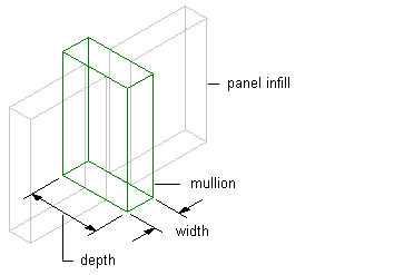
Specifying Door/Window Assembly mullion width and depth
Tip: To remove mullions for butt glazing, create a definition with both width and depth set to zero. Then assign that definition to the mullions that you want to remove.
-
Click

 .
.
- Expand Architectural Objects Door/Window Assembly Styles. Note: Alternatively, select a door/window assembly in the drawing, and click .

- Select a door/window assembly style.
- Click the Design Rules tab.
- In the left pane, select Mullions under Element Definitions.
- Click
 to create a new mullion definition.
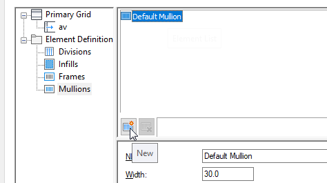
- Enter a descriptive name for the mullion definition.
- Specify a width and depth for the mullion definition.
- Specify any offsets.
- Click OK.
After you create a mullion definition, you can assign it to any mullion in a door/window assembly.