
Use this procedure to create a frame element definition from a profile. If you do not want a straight edge to your frame, you can use a profile to define edges with curves, jags, or any other shape you require.
You can also use an edit in-place routine to create a frame from a profile.
It is helpful to use a naming convention for profiles that indicates the grid location or purpose within the door/window assembly. For example, L3-FL1- Metal Frame identifies a metal frame in a third-level grid on Floor 1.
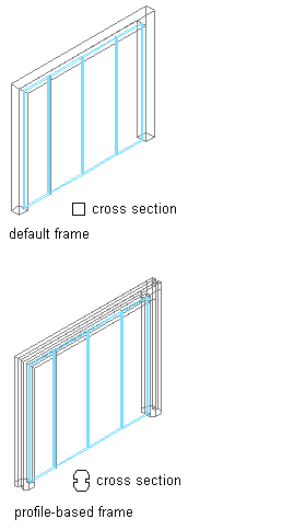
Specifying default and profile-based Door/Window Assembly frames
- Create the profile to use for the frame.
- Click
 .
. 
- Expand Architectural Objects Door/Window Assembly Styles. Note: Alternatively, select a door/window assembly in the drawing, and click .

- Select a door/window assembly style.
- Click the Design Rules tab.
- In the left pane, select Frames under Element Definitions.
- Select a frame definition or click
 to create a new one.
 - Enter a descriptive name for the frame.
- Specify a width and depth for the frame edge.
These dimensions are used to calculate the center point of the edge for aligning the profile and also to specify a boundary for the adjacent infill.
- Select Use Profile. Note: The Profile options are available only when you have profiles in the current drawing.
- Select a profile from the list.
By default, the profile is inserted using the same width and depth with which it was created.
- To adjust the size of the profile to fit within the width or depth dimension of the frame edge, select Auto-Adjust Profile Width or Depth.
- To mirror the profile along the X or Y axis, select X or Y for Mirror In.
- To rotate the profile, specify a rotation angle.
- Specify any offsets.
- Click OK.
After you create a frame definition, you can assign it to any frame in a door/window assembly.