
You can visualize the location of objects in relation to section views by adding projections and crossings to the section views.
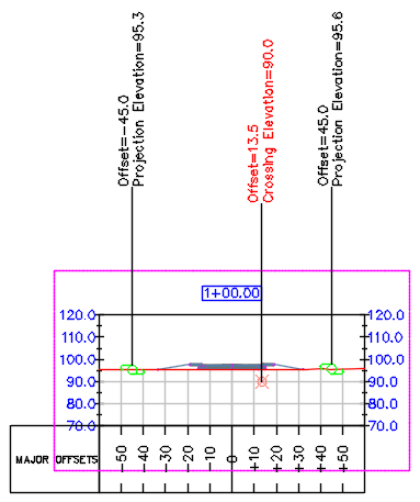
The following illustration shows projections on either side of the corridor at the existing ground level, and one crossing below ground level.
The following object types can be shown as projections and/or crossings in section views:
| Object Type | Projection | Crossing |
|---|---|---|
| Autodesk Civil 3D COGO points | Yes | Yes |
| AutoCAD points | Yes | Yes |
| 3D solids | Yes | Yes |
| blocks | Yes | Yes |
| multi-view blocks | Yes | Yes |
| 3D polylines | No | Yes |
| feature lines | No | Yes |
| survey figures | No | Yes |
Pipe networks have a separate procedure for projection into views. For more information, see About Displaying Pipe Networks in Profile Views and About Displaying Pipe Networks in Section Views.
Projections and Crossings
You can display both projections and crossings in section views.
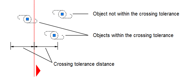
- Crossings can be shown in section views for objects that cross the sample lines or are within the crossing tolerance. A crossing is a marker in the section view that shows the location where the object crosses the sample line. If an object does not cross a sample line in plan view, or if it does not fall within the crossing tolerance, a crossing is not created for that object in section view.
A non-linear object such as a block is considered to be crossing a sample line if its centroid grip crosses the sample line, or is within the crossing tolerance.
You can specify a crossing tolerance value in the Edit Feature Settings - Section Views dialog box to control how close the centroid grip of an object can be to the sample line in order for it to be considered as crossing it.
 Note: The crossing tolerance does not apply to 3D solids, 3D polylines, feature lines, or survey figures, which are considered to be crossing only if they intersect a sample line.
 - Projections can be shown in section views for objects that are within the sampled width of the sections, or which meet the specified projection rules when projecting to multiple section views.
Note: 3D polylines, feature lines, and survey figures can be displayed as crossings, but not as projections.
Editing Projected Objects
The station location of a projected object always reflects the location of the source object, so it can only be changed by moving the source object.
The styles and elevations of projected objects can be edited on the Projections and Crossings tab of the Section View Properties dialog box and the Projections tab of the Profile View Properties dialog box.
The elevation of a projected object can be set to Use Object. This is a dynamic setting that ensures the elevation of the projected object and the source object are the same. If the source object is edited, the projected object reflects any changes. Elevations can also be set to match a surface (for projections in section view) or a surface or a profile (for projections in profile view).
The elevation of some projected objects can be edited using grips. The exceptions are three object types in profile views:
- Survey figures
- Feature lines embedded in a corridor
- Feature lines dynamic to an alignment
Grip editing the vertices of feature lines or 3D polylines in a profile view also changes the elevations of the source objects in plan view. This behavior is useful for editing feature lines in relation to profiles. Grips appear on 3D polylines only if the elevation is set to Use Object.
Grip editing point or block objects in profile or section views does not affect the elevations of source objects, but it does break the dynamic link to the source object elevation. The Elevation Options setting changes to Manual. At any time you can change this setting to Use Object, or to match a specific surface or profile.
The object and label styles of a projected object are independent of the styles used by the source object in plan view.
Projecting Multi-View Blocks
The display of a multi-view block in section or profile depends on the projection style. A projection style contains multiple display representations, which control how the multi-view block is represented in different contexts. Each display representation contains a set of view blocks that represent the object at different view directions. Each view block has a flag that indicates whether it will be drawn in any of the view directions.
When a multi-view block is drawn in Autodesk Civil 3D, the following process is performed:
- The appropriate view direction and display representation are obtained from the projection style.
- The applicable view blocks for the display representation are obtained.
- The view blocks are checked against the specified view direction, and the visible blocks are collected.
- The visible view blocks are rotated and vertically exaggerated as needed.
- The visible view blocks are drawn in section or profile view.