
In this exercise, you will create a corridor using existing vertical and horizontal geometry. You will modify the corridor in the intersection area, and then experiment with the corridor region recreation tools.
Create a corridor in the intersection area
- Open
Intersection-Edit-Corridor.dwg, which is located in the
tutorials drawings folder.
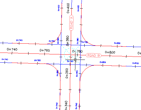
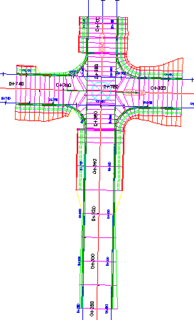
This drawing contains an intersection of a primary road (Road A) and a secondary road (Road B). There currently are no corridors or corridor assemblies in the drawing.
- Select the intersection marker.
- Click
tab
 panel Find.
The Intersection Corridor Regions dialog box is displayed.
- Under Select Surface To Daylight, select Existing Ground.
- Under Apply An Assembly Set, click Browse.
- In the Select Assembly Set File dialog box, navigate to the Assemblies folder.
- Select _Autodesk (Metric) Assembly Sets.xml. Click Open.
- Click
Recreate.
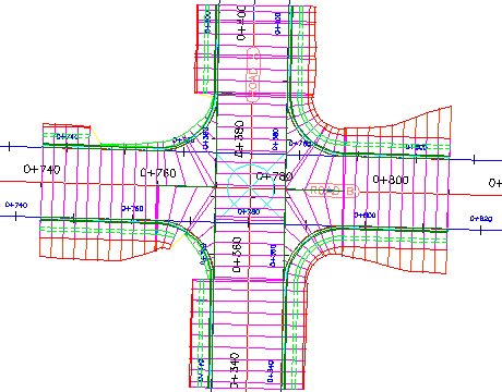
A corridor is displayed in the intersection area.
Modify the corridor properties
- In
Toolspace, on the
Prospector tab, expand the
Corridors and
 Intersections collections.
If either of the objects in these collections is
 out of date, right-click the object and select
Rebuild.
out of date, right-click the object and select
Rebuild.
- Select the corridor that is in the intersection area.
- Select the
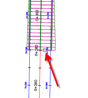
 grip that is at the bottom of the intersection. Drag the grip down. Click to place the grip further to the south.
- Click
tab panel drop-down Find.
- In the
Corridor Properties dialog box, on the
Parameters tab, click
 Select Region From Drawing.
- In the drawing, click the bottom of the corridor.
The specified region is highlighted in the Corridor Properties dialog box.
- In the highlighted row, in the
Frequency column, click
 .
.
- In the
Frequency To Apply Assemblies dialog box, under
Apply Assembly, specify the following parameters:
- Along Tangents: 10
- Along Curves: At An Increment
- Curve Increment: 5
- Along Spirals: 5
- Along Profile Curves: 5
- Click OK twice.
- In the Corridor Properties - Rebuild task dialog box, click Rebuild the Corridor.
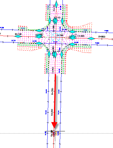
The corridor is rebuilt. The corridor extends further to the south. In the extended region, the assemblies are further apart than the intersection regions.
Recreate the corridor regions
- Select the intersection marker.
- Click
tab panel Find.
- Under Select Surface To Daylight, select Existing Ground.
- In the Intersection Corridor Regions dialog box, under Apply An Assembly Set, click Browse.
- In the Select Assembly Set File dialog box, navigate to the Assemblies folder.
- Select
_Autodesk (Metric) Assembly Sets.xml. Click
Open.
This is the assembly set that you used to create the corridor. However, Intersection Corridor Regions dialog box enables you to specify another assembly set, or individual assemblies, with which to create the corridor.
- Click
Recreate.
The corridor is recreated. Notice that the modifications that you made to the Road A baseline, including the assembly frequencies and region start station, returned to their original settings. This happened because the corridor was recreated using the parameters that were originally specified during the intersection creation process. Modifications that are made to the corridor in the intersection area are not retained when you recreate the corridor from the intersection object.
Note:Corridor regions that are outside the intersection extents are not affected by the Recreate Corridor Regions command.