
Use the Traverse Editor to create 2D traverses by entering data or by selecting a polyline from the drawing. After entering the data, you can send the traverse data to the Traverse Adjustment dialog box to apply an adjustment method.
Graphical Preview and Object Insertion
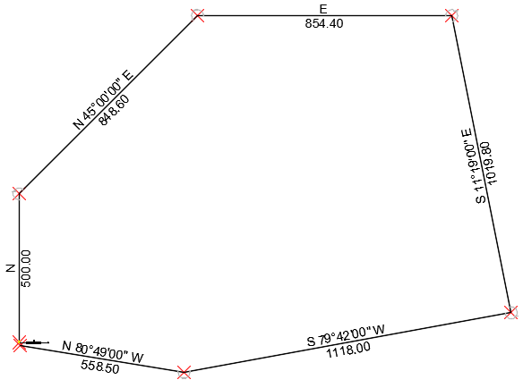
Graphics, as shown in the following example, are displayed in the drawing when you enter traverse data in the Traverse Editor.
You can specify whether you want to create points, lines, or points and lines in the drawing as you enter data. These objects remain in the drawing after you close the Traverse Editor.
The Traverse Editor has a zoom setting you can specify to control the view of the graphics. If the zoom setting is set to Zoom Current Row, the zoom level in the drawing is changed when you enter data for a traverse side as needed to display the traverse graphics in the drawing window. Alternately you can specify that the view is zoomed to show the extents of the traverse or that no zooming occurs.
General Guidelines for Entering Data
You can load data into the Traverse Editor by selecting an existing polyline in the drawing or by manually entering known data. You can use a variety of formats and mathematical equations to enter traverse data.
- Use the Tab, Enter, or arrow keys to navigate between cells.
- The values you enter in the Traverse Editor are not affected if the traverse is adjusted.
- If an initial backsight is not specified, a default backsight of East (AutoCAD 0 degrees) will be used. Enter N or S in the Angle field of the first row if you want to start turning from an azimuth.
- To use a unit of measure other than the current drawing unit, you can enter a suffix after the value. The following units are supported:
- Feet: '
- Meter: m
- Chain: c
- Rod: r
- Vara (Texas):
v
Note: 1 vara = 33 1/3 inches.
- Link: l
Enter the suffix directly after the value without adding an extra space. For example, to enter 10 feet, enter 10'.
Note: Converting between feet and meters depends on the parameters specified on the Units and Zone tab of the Drawing Settings dialog box:If Drawing Units is set to: and Imperial to Metric Conversion is set to: and the suffix is: then the distance conversion is: Feet US Survey Foot m meters to US survey foot Feet International Foot m meters to international foot Meters US Survey Foot ' US survey foot to meters Meters International Foot ' international foot to meters
Using Mathematical Equations to Calculate Traverse Parameters
You can enter a variety of mathematical equations to calculate traverse parameter values. The equations enable you to enter known data, such as the relative location of COGO points, when you define a traverse.
The following operators are valid:
- +
- -
- /
- *