Alignments tab
In addition to the standard column layout and labelling options, the Alignments tab in the Layout Options window provides a series of dedicated options for controlling the display and formatting of alignment and profile related station and entity data.
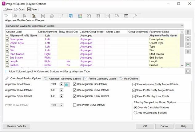
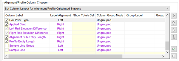
Alignment/Profile Column Chooser
- Set Column Layout for Calculated Stations in Centerline Alignments/Profiles
- Set Column Layout for Calculated Stations in Offset Alignments/Profiles
- Set Column Layout for Calculated Stations in Curb Return Alignments/Profiles
- Set Column Layout for Calculated Stations in Utility Alignments/Profiles
- Set Column Layout for Calculated Stations in Rail Alignments/Profiles
Calculated Stations Options
These settings control the content of the Calculated Stations sub-object list for alignments and profiles.
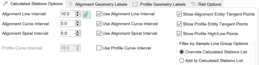
Alignment interval related settings
Set the station sampling interval for alignments on line, spiral, and curve entities. Optionally, the interval for certain entity types can be disabled which can be useful if you only need interval points on spirals or curves. To use a common alignment interval for all entity types, use the Lock Station Intervals check button.
Profile interval related settings
The alignment interval settings may not be adequate alone to provide sufficient detail on alignment/profile combinations along curved profile entities. If this is the case, enabled the Use Profile Curve Interval option in conjunction with the Profile Curve Interval parameter to override the alignment interval settings where the profile passes through a curved profile entity.
Include/exclude geometry points
By default, the start and end points for every alignment and profile entity will be included in the Calculated Stations list, along with high and low elevation points for each profile. In situations where you want to extract station samples at the quoted station intervals only, these options can be disabled to prevent the extra geometry points from being included in the list.
Filter by Sample Line Group Options
These settings refer to the Sample Line Group Filter on the Alignment tab.
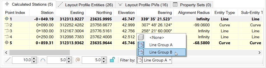
By default, The Override Calculated Stations list option is selected which only shows the sample line group stations. Selecting Add to Calculated Stations List will display both the calculated interval stations and those from the selected sample line group.
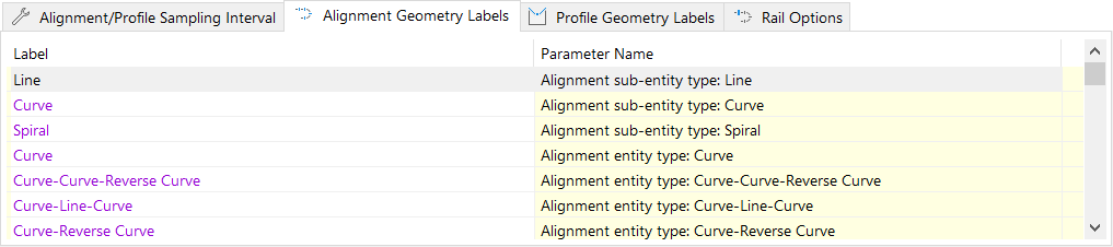
Alignment geometry labels
This set of options provides control over any localizable or customizable phrases for alignment entity or sub-entity types, spiral types, constraint types, and point types that appear in the Project Explorer user interface or in outgoing reports, spreadsheets, and AutoCAD tables.
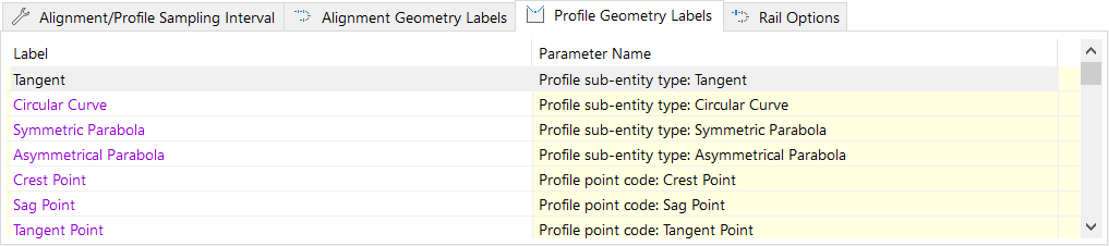
Profile geometry labels
This set of options provide control over any localizable or customizable phrases for profile entity types, constraint types, curve types, and point types that appear in the Project Explorer user interface or in outgoing reports, spreadsheets, and AutoCAD tables
The Layout Options window is used to control both the layout of outgoing reports and the layout of the Project Explorer window. The effect of editing a value in this window therefore depends on the scope in which the window was opened. Refer to the Introduction topic for the Layout Options Window for further details.
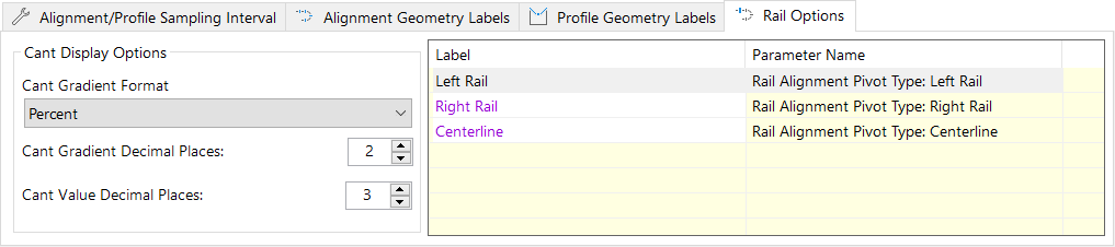
Rail Options
The Rail Options tab features Cant Display Options and a list label list. You can use the Cant Display Options box to control the Cant Gradient value in Cant Curves tab. The label list allows you to edit the name of rail labels in the drawing. After editing a label in the Rail Options dialog, labels in the Project Explorer main window, Alignments tab, Calculated Stations list, and Rail Pivot Type are updated.