
The compass is a guide which you can use during pressure network layout to insert the next pressure network part. The compass appears as a circle and tick marks after the first pipe segment is drawn. The tick marks show the angles that can be established with the available bends or the allowable deflection angles.
To turn on compass visibility
- Click Compass panel
 Visibility
 .
.
Click again to hide the compass.
To turn on compass snapping
- Click Compass panel Snapping
 .
.
Click again to turn off snapping. You can then place the pressure pipe at any angle.
To change the compass color
- Click Compass panel drop-down and then select a color from the drop-down list.
To change the compass diameter
- Click Compass panel drop-down and then specify a diameter.
The compass displays the angles of bends in the current parts list that match the selected pipe size and material.
For example, in the illustration below, the compass shows that 11.25, 22.5, 45, and 90 degree bends are available. This means that for the selected pipe size and material, there are also 11.25, 22.5 45, and 90 degree bends defined for that same material and nominal diameter in the current parts list.
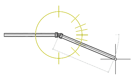
The compass constrains your selections to these available angles. The angle that your cursor is closest to when you click to establish the next point in the pressure network is snapped to. For example, a 22.5 degree bend will be inserted into the drawing if the pointing device is clicked in the current position.
If you select a different pipe size and material during layout, the compass tick marks are updated to display the angles of the bends or the allowable deflection angles for the current pipe size and material.
To use the compass
- When a layout command is active (including when a Continue Layout grip is selected) the compass displays the angles of the bends or the allowable deflection angles for the current pipe size and material. Move your cursor to snap to one of the available angles, and then click your cursor to establish the next pressure network segment in the drawing.