
Create a single profile view to display a surface profile and to design a layout profile. Each profile view displays new or existing profiles and offsets for one horizontal alignment.
![]() Tutorial: Displaying and Modifying Profile Views
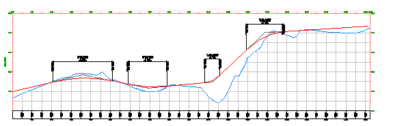
Tutorial: Displaying and Modifying Profile Views
-
Click
 Find.
Find.
- In the Create Profile View wizard, navigate through the pages by using the links at the left or clicking Back or Next. Note: Click Create Profile View at any time to accept the current settings.
The wizard pages contain the following controls:
- General page - Specify the alignment name and profile view name and description. Note: The Show Offset Profiles By Vertically Stacking Profile Views is only applicable when creating stacked profile views.
- Station Range page - Specify the starting and ending stations.
- Profile View Height page - Specify the profile view height and any split profile options, including split stations and styles for individual stations.
- Profile Display Options page - Specify the profiles to be drawn as well as their styles, labels, and layers.
- Pipe/Pressure Network page - Specify the pipe networks or parts to be drawn.
- Data Bands page - Specify the data band sets and their properties.
- Hatch Options page - Specify how to mark areas between two profiles on the profile view, such as where terrain must be cut or filled to create the design profile.
- General page - Specify the alignment name and profile view name and description.
- Click Create Profile View.
- In the drawing window, click a location for the lower left corner (origin) of the profile view grid. The profile view is drawn.