
Settings in Autodesk Civil 3D control many preset values, such as drawing units, scale, and coordinate system.
Autodesk Civil 3D has drawing, feature, and command settings. All three levels of settings in Autodesk Civil 3D are saved with the drawing, and they can be saved to a drawing template.
- Drawing settings establish values for the whole drawing. If you are creating a drawing template, ensure that these are set correctly. All commands use the drawing settings unless there is a specific override at the feature or command level.
- Feature settings control behavior for a particular feature, such as Parcels or Grading.
- Command settings apply to individual commands within a feature, such as the CreateParcelByLayout command within the Parcels feature.
You modify each level of settings at a different location in the Settings tree, as shown in the following illustration:
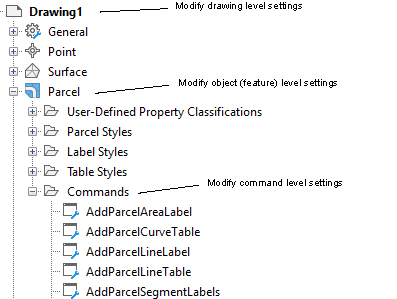
Drawing-Level Settings
There are two types of drawing-level settings:
- Drawing-wide settings, which include units and zone, transformation settings, abbreviations, and object layers.
- Ambient settings, which affect a variety of Autodesk Civil 3D behaviors. You can change ambient settings at the drawing level, and you can also override ambient setting values at either the object level or the command level.
You access drawing-level settings by right-clicking the drawing name in the Settings tree and clicking Edit Drawing Settings.
At the drawing level, the Edit Settings dialog box contains only the ambient settings for the drawing:
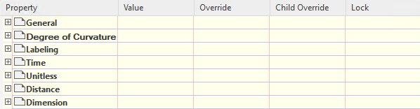
The following summarizes the controls in the Edit Settings dialog box:
- Use the + or – boxes to display or hide the settings in the category.
- Use the Value column to specify a value for a setting.
- The Override column indicates that the default value has been changed for the setting.
- The Child Override column indicates whether the setting has been overridden at a lower level in the Settings tree.
- Use the Lock column to control whether a setting can be changed at a lower level in the Settings tree.
Object (Feature)-Level Settings
Use the object collection level in the Settings tree to control all settings that pertain to the object type. Change the object settings at this level in the tree, and specify overrides for the drawing ambient settings.
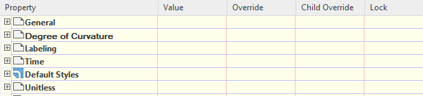
Access the object- or feature-level settings by right-clicking the object collection in the Settings tree and clicking Edit Feature Settings.
At the object level, this dialog box also contains object-specific settings, such as default styles:
Command-Level Settings
Use the Commands collection level in the Settings tree to override both the object-level settings and drawing ambient settings on a command-by-command basis. You can also specify command-specific settings.
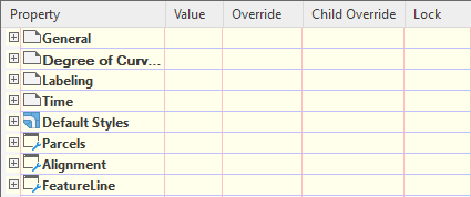
Access the command-level settings by expanding the Commands collection for an object type in the Settings tree, right-clicking the command, and clicking Edit Command Settings.
At the command level, this dialog box also contains command-specific settings, such as the Parcels and Alignments settings that are used by the CreateSite command.
Inheriting and Overriding Settings
Each lower level object in the settings hierarchy can either inherit or override settings in the level above it. The following illustration shows an override set for area units at the Parcels feature level.
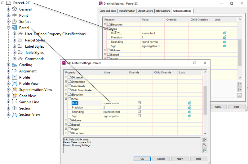
Feature settings can override drawing settings
The arrow in the Child Override column of the Drawing Settings dialog box (upper dialog box) indicates that an override has been set at a lower level.
The check mark in the Override column in the Edit Feature Settings - Parcel dialog box (lower dialog box) indicates that the value set in this dialog box overrides the setting at a higher level.
At the drawing level you can cancel a child override by clicking the arrow icon in the Child Override column. This causes the arrow icon to appear as follows:
 .
.
You can prevent overrides by locking a setting.