
In this exercise, you will configure the drawing window, using named views and viewports.
Divide the drawing area into separate viewports
- Open
Intro-2.dwg, which is located in the
tutorials drawings folder.
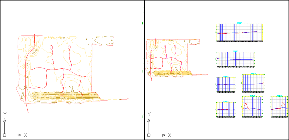
This drawing contains an existing ground surface, several alignments, and several profile views that contain existing ground and layout profiles.
- Click
View tab
 Model Viewports panel Viewport Configuration ListTwo: Vertical.
Two viewports are displayed. Each viewport is a separate window in which you can pan and zoom to different views of the drawing. You can create custom viewport configurations and save them for later use.
- Click in each of the viewports.
Notice that as you click in a viewport, the border darkens to indicate which viewport is currently active. Click the viewport on the left side to make it active.
- On the command line, enter
ZE.
The surface and profile views are displayed in the left viewport.
Apply a saved drawing view
- Click the viewport on the left side to make it active.
- Click
tab panel .
The extents of the EG surface appears in the left viewport.
Three views have been created in this drawing. Each named view consists of a specific magnification, position, orientation, and layer status. Named views are saved with a drawing and can be used any time. When your drawing is displaying a specific view to which you want to return, you can save it as a named view by clicking tab
panel .
To continue this tutorial, go to Exercise 2: Changing the Display of an Object.