By default, Autodesk Civil 3D joins all points with the same point code along a corridor baseline and displays them as feature lines. You can modify how points are connected when a point code is used multiple times at consecutive stations.
Modify feature line connections by specifying which point codes are connected using branching options and the direction for branching, and whether extra point codes are to be connected.
Branching and Connecting Extra Points
If an assembly is applied at consecutive stations with a varying number of point codes (of the same type), you can control both whether the feature lines are connected and how they are connected.
The following illustrations show different branching and point connection options and the resultant feature lines.
In all illustrations:
- Assemblies with a varying number point codes of the same type are used at the stations.
- The centerline (heavy black line) is the corridor baseline (alignment).
- The circular points on the gray lines are of one type of point code.
- The circular points on the green lines are of another type point code.
- There are two groups in each assembly: left and right (of the baseline).
- The Connect option is selected for both types of point codes.
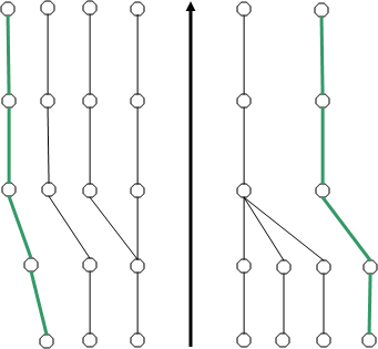
Inward branching and extra points (with the same point code) are not connected:
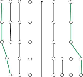
Inward branching and extra points (with the same point code) are connected:
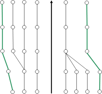
Outward branching and extra points (with the same point code) are not connected:
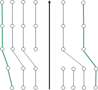
Outward branching and extra points (of the same point type) are connected: