CADmep can output Piping Component File (PCF) format that can be used for analysis in other products, such as AutoCAD Plant 3D.
PCF is an industry-standard file format that enables automatic generation of isometric spool drawings.
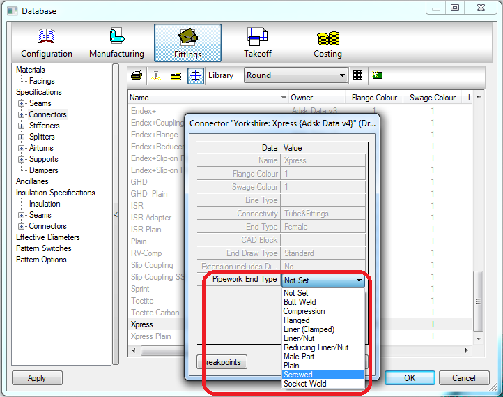
Setting Pipework End Type
In order to output CADmep models to PCF format, the "Pipework End Type" parameter must be set on all connectors to be exported.
- Not Set (As noted, this is the only setting that is not allowed for PCF export.)
- Butt Weld
- Compression
- Flanged
- Liner (Clamped)
- Liner/Nut
- Reducing Liner/Nut
- Male Part
- Plain
- Screwed
- Socket Weld
To set the Pipework End Type, or to determine if it has been set, go to Database
 Fitting
 Connector
 Pipework End Type. Ensure that the appropriate connection type has been set on the Pipework End Type property.

To output PCF files:
- In CADmep, do one of the following:
- In the drawing area, right-click CADmep
 Utilities
 Export PCF File.
- At the command line, type PCFEXPORT and then press Enter.
- In the drawing area, right-click CADmep
- On the Export as PCF dialog, choose a location to save the PCF file, and type in a file name.
- Click Save.
Setting PCF Symbol Key (SKEY)
In CADmep, the PCF export function also supports the export of PCF SKEY values. When this information is specified on items, it is included in the PCF export file.
For more information, see Specifying PCF Symbol Key (SKEY) Values and Item Properties.
