
Set the injection location
In this task you will learn how to choose and set a suitable injection location, using the Gate Location analysis to suggest appropriate injection locations based on the geometry of the part.
Click
 ( Home tab > Molding Process Setup > Analysis Wizard).
Select the Gate Location checkbox and then click Next.
From the Gate locator algorithm drop-down list, select Gate Region Locator.
Click Analyze.
When the Analysis Complete! dialog box appears, click OK.
Click Best Gate Location result in the Study Tasks pane.
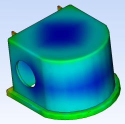
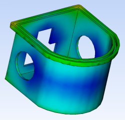
Gate Location analyses, using the Gate Region locator algorithm, output one result. The Best Gate Location result indicates that the best location for the gate would be within a blue region such as the center top of the part.
Consider the following design criteria when you view the Best Gate Location result, before you select the injection location.
- Functionality of the part
- Geometry of the part
- Type of feed system
- Mold requirements
- To be able to mold the holes on the three sides of the part and still be able to eject the part, moving cores are required. The slides required for these cores restrict the final location of the sprue and runner system.
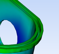
As a result of these considerations, one possible position for the injection location is on the bottom rounded edge of the part. Use the Best Gate Location result to help you determine the suitability of this position from a processing perspective.
Click
 ( Results tab > Examine panel > Examine).
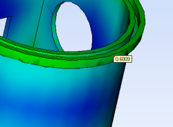
The higher the numerical value displayed by the Examine Result tool, the more suitable the location is for the gate.
Click on the rounded lip of the part to find a high numerical value.
In this example, the Best gate location result of about 0.60 (or 60%) shows this to be an acceptable location to use.
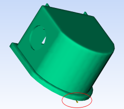
Rotate the model so that it appears as shown below.
Click
 (Home tab > Molding Process Setup panel > Injection Locations).
A dialog appears warning you that study results are about to be deleted.
Click Delete.
Click on the rounded lip of the model as shown below.
Right-click in the Model pane and select Finish Set Injection Locations from the menu.
You can position the injection location more accurately by entering the coordinates you require.
Right click the injection cone, and select Properties.
The Edit properties panel appears which allows you to specify the coordinates of the injection location.
Enter the following values:
- X: 0
- Y: 6.93
- Z: 66.5
Click Apply.
The injection location is now positioned on the rounded lip of the model.