
Warpage Constraints dialog
To access this dialog, run a Warp analysis, select the Warp page in the Summary pane, and then select a Warp result.
 (Results tab > Results panel > Warpage Constraints).
The top section of this dialog allows you to define the X, Y and Z coordinates for the points used to define warpage in the model.
There are two ways that warpage can be displayed:
Anchor Plane
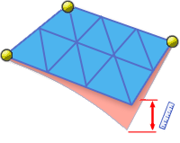
The Anchor Plane option allows you to define three points on your model that define the anchor plane used to calculate the model warpage.
The first point defined is the anchor point.
It is constrained in all directions
 (X, Y, Z).
The second point defined is constrained to move only in the
 (X) direction.
The third point defined is constrained to move in both the
 (X and Y ) direction.
Tip: To resize the anchor plane icons, hold-down the shift key, click and hold the left mouse button, and move the cursor up and down the screen. You can also select an anchor and drag it to a new location.
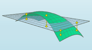
Best Fit
- The Best Fit option uses reference points. Reference points are positions on the part that need to be monitored for dimensional compliance. There is no limit to how many reference points can be defined. Minimizing the average deflection of the reference points, determines the Best Fit plane and the inclination of the plane relative to the part. Deflection results for the rest of the part are then taken relative to the Best Fit plane.
The Nominal Maximum Deflection section of this dialog is used for a Warpage Indicator result to specify the maximum allowable out-of-plane deflection in the part. This information is used to assess the level of warpage in different regions of the model.
Dialog elements
| Anchor plane | Use an anchor plane to measure the deflection of the part against a specified plane. |
| Best fit | Use the Best fit technique to measure the deflection of the part against a plane that is orientated so that the deformed geometry is positioned in such a way that the total displacement is as small as possible. This is the default method. If reference points have been selected, it is these points only that the total displacement is minimized for. |
| X, Y and Z coordinates | Click the model or enter the X, Y and Z coordinates to specify the points on your model that will be used to calculate the part deflection. |
| List of reference points | Contains the list of all reference points that have been specified. |
| Add | Adds the X, Y and Z coordinates to the list of reference points. |
| Delete | Deletes the selected coordinates from the list of reference points. |
| Modify | Alter the selected coordinates. |
| Nominal maximum deflection | Specify the maximum allowable out-of-plane deflection value to be used in the warpage assessment. |
| Restore default value | Sets the Nominal maximum deflection back to its default value. |